


210
Communication operation and setting
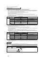
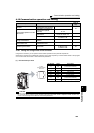
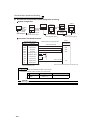
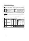
(2) PU connector communication system configuration and wiring
z System configuration
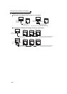
z Connection with RS-485 computer
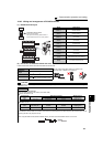
* Make connections in accordance with the manual of the computer used. Fully check the terminal numbers of the computer since
they change with the model.
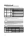
REMARKS
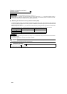
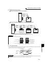
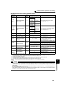
⋅ Refer to the following when fabricating the cable on the user side.
Commercially available product examples (as of October 2008)
* Do not use pins No. 2, 8 of the communication cable.
CAUTION
When performing RS-485 communication with multiple inverters, use the RS-485 terminals. (Refer to page 212)
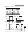
PU
connector
Inverter
Station 0
Computer
PU
connector
Inverter
FR-DU07
Communication cable 1)
RJ-45 connector
RJ-45 connector
PU
connector
Inverter
Station 0
Computer
Communication cable 1)Communication cable 1)
RS-232C-RS-485
converter
RS-232C
cable
Operation
panel
connector
FR-ADP
(option)
RS-485
interface/
terminals
RJ-45
connector
RJ-45
connector
Maximum
15m
RS-232C
connector
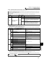
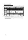
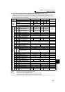
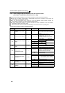
Computer Side Terminals
Send data
Send data
Receive data
Receive data
Description
Frame ground
Signal ground
Clear to send
Clear to send
Request to send
Request to send
SDB
SDA
RDB
RDA
Signal name
FG
SG
CSB
CSA
RSB
RSA
RDB
RDA
SDB
SDA
PU connector
RS-485 terminal
SG
Inverter
*
0.2mm
2
or more
Cable connection and signal direction
Communication cable
Product Type Maker
1)
Communication
cable
SGLPEV-T (Cat5e/300m)
24AWG × 4P *
Mitsubishi Cable Industries, Ltd.