


131
Function assignment of external
terminal and control
4
PARAMETERS
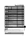
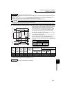
(2) Inverter operation ready signal (RY signal) and inverter running signal (RUN, RUN3 signal)
*1 This signal turns OFF during power failure or undervoltage.
*2 Output is shutoff in conditions like a fault and when the MRS signal is ON.
REMARKS
⋅ The same function may be set to more than one terminal.
⋅ When the function is executed, the terminal conducts at the setting of any of "0" to "99", and does not conduct at the setting of
any of "100" to "199".
⋅ When Pr. 76 Fault code output selection = "1", the output signals of the terminals SU, IPF, OL and FU are switched as set in Pr. 76.
(When an inverter fault occurs, the signal output is switched to the fault code output.)
⋅ The output assignment of the terminal RUN and fault output relay are as set above regardless of Pr. 76.
CAUTION
⋅ Changing the terminal assignment using Pr. 190 to Pr. 196 (output terminal function selection) may affect the other functions.
Please set parameters after confirming the function of each terminal.
⋅ Do not assign signals which repeat frequent ON/OFF to A1 B1 C1, A2 B2 C2. Otherwise, the life of the relay contact decreases.
⋅
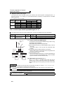
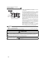
When the inverter is ready to operate, the output of the operation
ready signal (RY) is ON. It is also ON during inverter running.
⋅ When the output frequency of the inverter rises to or above
Pr. 13 Starting frequency, the output of the inverter running
signal (RUN) is turned ON. During an inverter stop or DC
injection brake operation, the output is OFF.
⋅ The output of the RUN3 signal is ON when the inverter
running and start signals are ON.
(For the RUN3 signal, output is ON if the starting command is
ON even when a fault occurs or the MRS signal is ON.
⋅
When using the RY, RUN and RUN3 signals, assign functions to
Pr. 190 to Pr. 196 (output terminal selection function) referring to the
table below.
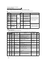
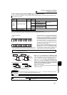
Inverter
Status
Output
Signal
Start
Signal is
OFF
(during
stop)
Start
Signal is
ON
(during
stop)
Start
Signal is
ON
(during
running)
Under DC
Injection
Brake
Output Shut Off
*2
Automatic Restart after
Instantaneous Power Failure
Coasting
Restarting
Start signal
is ON
Start signal
is OFF
Start signal
is ON
Start signal
is OFF
RY ON ON ON ON OFF ON *1 ON
RUN OFF OFF
ON OFF OFF OFF ON
RUN3 OFF
ON ON ON ON OFF ON OFF ON
REMARKS
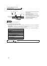
⋅ RUN signal is assigned to the terminal RUN in the initial setting.
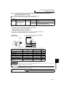
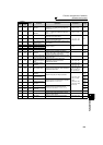
RUN
Power
supply
Output frequency
STF
RH
RY
RUN3
Pr. 13
Starting
frequency
DC injection brake
operation point
DC injection
brake
operation
Reset
processing
Time
ON
ON
ON
ON
ON
ON
OFF
OFF
OFF
OFF
OFF
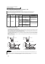
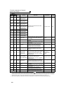
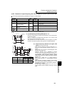
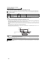
Output
Signal
Pr. 190 to Pr. 196 Setting
Positive logic Negative logic
RY 11 111
RUN 0100
RUN3
45 145