


207
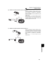
Selection of operation mode and
operation location
4
PARAMETERS
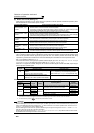
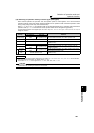
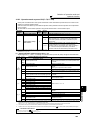
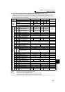
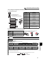
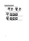
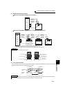
(5) Selection of command source in Network operation mode (Pr. 338, Pr. 339)
⋅ There are two control sources: operation command source, which controls the signals related to the inverter start
command and function selection, and speed command source, which controls signals related to frequency setting.
⋅ In Network operation mode, the commands from the external terminals and communication (RS-485 terminals or
communication option) are as listed below.
[Explanation of table]
External : Command only from control terminal signal is valid.
NET : Command only from communication is valid
Combined : Command from either of external terminal and communication is valid.
⎯ : Command from either of external terminal and communication is invalid.
Compensation : Command by signal from external terminal is only valid when Pr. 28 Multi-speed input compensation selection = "1"
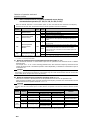
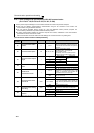
Operation
Location
Selection
Pr. 338 Communication operation command source
0: NET 1: External
Remarks
Pr. 339 Communication speed command source 0: NET
1:External 2:External
0: NET
1:External 2:External
Fixed function
(Terminal-
equivalent
function)
Running frequency from communication
NET
⎯
NET NET
⎯
NET
Terminal 2
⎯
External
⎯⎯
External
⎯
Terminal 4
⎯
External
⎯
External
Terminal 1
Compensation
Selective function
Pr. 178 to Pr. 189 setting
0RL
Low speed operation command/
remote setting clear
NET External NET External
Pr. 59 = "0" (multi-
speeds)
Pr. 59 = "1 , 2"
(remote)
1RM
Middle-speed operation command/
remote setting deceleration
NET External NET External
2RH
High speed operation command/
remote setting acceleration
NET External NET External
3 RT Second function selection
NET External
4 AU Terminal 4 input selection
⎯
Combined
⎯
Combined
5 JOG Jog operation selection
⎯
External
6CS
Selection of automatic restart after
instantaneous power failure
External
7 OH External thermal relay input
External
8 REX 15-speed selection NET External NET External
Pr. 59 = "0"
(multi-speeds)
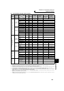
10 X10
Inverter run enable signal
External
11 X11
FR-HC or MT-HC connection,
instantaneous power failure detection
External
12 X12
PU operation external interlock
External
13 X13
External DC injection brake
operation is started
NET External
14 X14 PID control valid terminal
NET External NET External
16 X16 PU/External operation switchover
External
24 MRS
Output stop
Combined External
Pr. 79
≠ "7"
PU operation interlock
External
Pr. 79 = "7"
When X12 signal
is not assigned
25
STOP
Start self-holding selection
⎯
External
50
SQ
Sequence start NET External
51 X51 Fault clear signal Combined External
60 STF Forward rotation command NET External
61 STR Reverse rotation command NET External
62 RES Reset External
63 PTC PTC thermistor input External
64 X64 PID forward action switchover NET External NET External
65 X65 PU/NET operation switchover External
66 X66
External/NET operation switchover
External
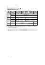
67 X67 Command source switchover External
70 X70
DC feeding operation permission
NET External
71 X71
DC feeding cancel
NET External
72 X72
PID integral value reset
NET External NET External
77 X77
Pre-charge end command
NET External NET External
78 X78
Second pre-charge end command
NET External NET External