


343
Causes and corrective actions
5
PROTECTIVE FUNCTIONS
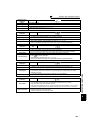
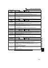
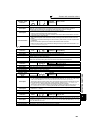
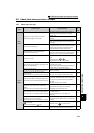
Operation Panel
Indication
E. 1
E. 2
FR-PU04
FR-PU07(-01)
Fault 1, Fault2
Name
Option fault
Description
Stops the inverter output when a contact fault is found between the inverter and the plug-in option, or
when the communication option is connected to a connector other than the bottom connector.
Appears when the switch for the manufacturer setting of the plug-in option is changed.
Check point
· Check that the plug-in option is plugged into the connector securely.
(1 and 2 indicate the option connector numbers.)
· Check for excess electrical noises around the inverter.
· Check that the communication option is not fitted to the connector other than the bottom connector.
Corrective action
· Connect the plug-in option securely.
· Take measures against noises if there are devices producing excess electrical noises around the
inverter.
If the problem still persists after taking the above measure, please contact your sales representative
or distributor.
· Fit the communication option to the connector other than the bottom connector.
· Return the switch position for the manufacturer setting of the plug-in option to the initial status. (Refer
to instruction manual of each option)
... Specifications differ according to the date assembled. Refer to page 400 to check the SERIAL number.
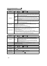
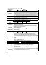
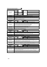
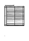
Operation Panel
Indication
E.PE
FR-PU04
FR-PU07(-01)
Corrupt Memry
Name
Parameter storage device fault (control circuit board)
Description
Trips when a fault occurred in the parameter stored. (EEPROM failure)
Check point
Check for too many number of parameter write times.
Corrective action
Please contact your sales representative.
When performing parameter write frequently for communication purposes, set "1" in Pr. 342 to enable
RAM write. Note that powering OFF returns the inverter to the status before RAM write.
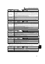
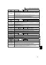
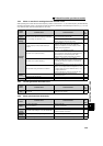
Operation Panel
Indication
E.PE2
FR-PU04 Fault 14
FR-PU07(-01) PR storage alarm
Name
Parameter storage device fault (main circuit board)
Description Trips when a fault occurred in the parameter stored. (EEPROM failure)
Check point ——————
Corrective action Please contact your sales representative.
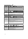
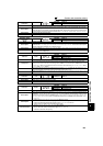
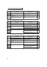
Operation Panel
Indication
E.PUE
FR-PU04
FR-PU07(-01)
PU Leave Out
Name
PU disconnection
Description
· This function stops the inverter output if communication between the inverter and PU is suspended,
e.g. the operation panel and parameter unit is disconnected, when "2", "3", "16" or "17", "102", "103",
"116" or "117" was set in Pr. 75 Reset selection/disconnected PU detection/PU stop selection.
· This function stops the inverter output when communication errors occurred consecutively for more
than permissible number of retries when a value other than "9999" is set in Pr. 121 Number of PU
communication retries during the RS-485 communication with the PU connector.
· This function stops the inverter output if communication is broken for the period of time set in Pr. 122
PU communication check time interval during the RS-485 communication with the PU connector.
Check point
· Check that the FR-DU07 or parameter unit (FR-PU04/FR-PU07) is fitted tightly.
· Check the Pr. 75 setting.
Corrective action
Fit the FR-DU07 or parameter unit (FR-PU04/FR-PU07) securely.
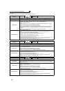
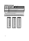
Operation Panel
Indication
E.RET
FR-PU04
FR-PU07(-01)
Retry No Over
Name
Retry count excess
Description
If operation cannot be resumed properly within the number of retries set, this function trips the inverter.
Functions only when Pr. 67 Number of retries at fault occurrence is set. When the initial value (Pr. 67 = "0")
is set, this fault does not occur.
Check point
Find the cause of fault occurrence.
Corrective action
Eliminate the cause of the fault preceding this error indication.