


297
Special operation and frequency control
4
PARAMETERS
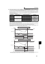
(3) Operating procedure
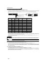
⋅ Procedure for operation
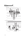
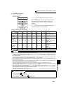
Operation pattern
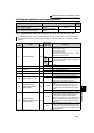
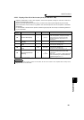
2)Signal ON/OFF after parameter setting
MRS CS STF MC1 MC2 MC3 Remarks
Power supply
ON
OFF
(OFF)
OFF
(OFF)
OFF
(OFF)
OFF
→
ON
(OFF
→
ON)
OFF
(OFF)
OFF
→
ON
(OFF
→
ON)
External operation mode
(PU operation mode)
At start
(inverter)
OFF
→
ON OFF
→
ON OFF
→
ON
ON OFF ON
At constant
speed
(commercial
power supply)
ON
ON
→
OFF
ON ON
OFF
→
ON ON
→
OFF
MC2 turns ON after MC3
turns OFF
(coasting status during this
period)
Waiting time 2s
Switched to
inverter for
deceleration
(inverter)
ON
OFF
→
ON
ON ON
ON
→
OFF
OFF
→
ON
MC3 turns ON after MC2
turns OFF
(coasting status during this
period)
Waiting time 4s
Stop ON ON
ON
→
OFF
ON OFF ON
CAUTION
⋅ Connect the control power supply (R1/L11, S1/L21) in front of input side MC1. If the control power supply is connected behind
input side MC1, the electronic bypass sequence function is not executed.
⋅ The electronic bypass sequence function is valid only when Pr. 135 = "1" in the external operation or combined operation mode
(PU speed command, external operation command Pr. 79 = "3"). When Pr. 135 = "1" in the operation mode other than the above,
MC1 and MC3 turn ON.
⋅ When the MRS and CS signals are ON and the STF (STR) signal is OFF, MC3 is ON, but when the motor was coasted to a stop
from bypass operation last time, a start is made after the time set to Pr. 137 has elapsed.
⋅ Inverter operation can be performed when the MRS, STF (STR) and CS signals turn ON. In any other case (MRS signal - ON),
bypass operation is performed.
⋅ When the CS signal is turned OFF, the motor switches to bypass operation. However, when the STF (STR) signal is turned
OFF, the motor is decelerated to a stop in the inverter operation mode.
⋅ When both MC2 and MC3 are OFF and either MC2 or MC3 is then turned ON, there is a waiting time set in Pr. 136.
⋅ If electronic bypass sequence is valid (Pr. 135 = "1"), the Pr. 136 and Pr. 137 settings are ignored in the PU operation mode. The
input terminals (STF, CS, MRS, OH) of the inverter return to their normal functions.
⋅ When the electronic bypass sequence function (Pr. 135 = "1") and PU operation interlock function (Pr. 79 = "7") are used
simultaneously, the MRS signal is shared by the PU operation external interlock signal unless the X12 signal is assigned.
(When the MRS and CS signals turn ON, inverter operation is enabled)
⋅ Changing the terminal function using any of Pr. 178 to Pr. 189, 190 to Pr. 196 may affect the other functions. Please set
parameters after confirming the function of each terminal.
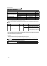
♦ Parameters referred to ♦
Pr. 11 DC injection brake operation time Refer to page 112
Pr. 57 Restart coasting time Refer to page 152
Pr. 58 Restart cushion time Refer to page 152
Pr. 79 Operation mode selection Refer to page 195
Pr. 178 to Pr. 189 (Input terminal function selection) Refer to page 122
Pr. 190 to Pr. 196 (Output terminal function selection) Refer to page 128
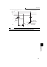
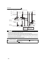
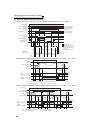
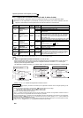
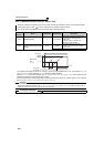
Power supply ON
Setting the parameters
Start inverter operation
Constant-speed bypass
operation
Deceleration (stop)
inverter operation
⋅ Pr. 135 = "1" (open collector output terminal of inverter)
⋅ Pr. 136 = "2.0s"
⋅ Pr. 137 = "1.0s" (Set the time longer than the time from when
MC3 actually turns ON until the inverter and motor are
connected. If the time is short, a restart may not function
properly.)
⋅ Pr. 57 = "0.5s"
⋅ Pr. 58 = "0.5s" (Be sure to set this parameter when bypass
operation is switched to inverter operation.)