


342
Causes and corrective actions
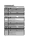
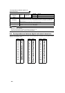
Operation Panel
Indication
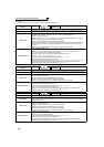
E.OHT
FR-PU04
FR-PU07(-01)
OH Fault
Name
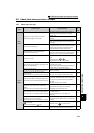
External thermal relay operation
Description
If the external thermal relay provided for motor overheat protection, or the internally mounted
temperature relay in the motor, etc. switches ON (contacts open), the inverter output is stopped.
Functions when "7" (OH signal) is set to any of Pr. 178 to Pr. 189 (input terminal function selection).
When the initial value (without OH signal assigned) is set, this protective function does not function.
Check point
· Check for motor overheating.
· Check that the value of 7 (OH signal) is set correctly in any of Pr. 178 to Pr. 189 (input terminal function
selection).
Corrective action
· Reduce the load and operating duty.
· Even if the relay contacts are reset automatically, the inverter will not restart unless it is reset.
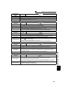
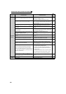
Operation Panel
Indication
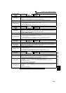
E.PTC
FR-PU04 Fault 14
FR-PU07(-01) PTC activated
Name
PTC thermistor operation
Description
Trips when the motor overheat status is detected for 10s or more by the external PTC thermistor input
connected to the terminal AU.
This fault functions when "63" is set in Pr. 184 AU terminal function selection and AU/PTC switchover
switch is set in PTC side. When the initial value (Pr. 184 = "4") is set, this protective function does not
function.
Check point
· Check the connection between the PTC thermistor switch and thermal relay protector.
· Check the motor for operation under overload.
· Is valid setting ( = 63) selected in Pr. 184 AU terminal function selection ? (Refer to page 110, 122.)
Corrective action Reduce the load weight.
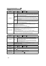
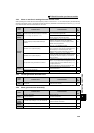
Operation Panel
Indication
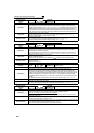
E.OPT
FR-PU04
FR-PU07(-01)
Option Fault
Name
Option fault
Description
· Appears when the AC power supply is connected to the terminal R/L1, S/L2, T/L3 accidentally when
a high power factor converter is connected.
· Appears when the switch for the manufacturer setting of the plug-in option is changed.
· Appears when a communication option is connected while Pr. 296 = "0 or 100".
Check point
· Check that the AC power supply is not connected to the terminal R/L1, S/L2, T/L3 when a high
power factor converter (FR-HC, MT-HC) or power regeneration common converter (FR-CV) is
connected.
· Check if password lock is activated by setting Pr. 296 = "0, 100"
Corrective action
· Check the parameter (Pr. 30) setting and wiring.
· The inverter may be damaged if the AC power supply is connected to the terminal R/L1, S/L2, T/L3
when a high power factor converter is connected. Please contact your sales representative.
· Return the switch for the manufacturer setting of the plug-in option to the initial status. (Refer to
instruction manual of each option)
· To apply the password lock when installing a communication option, set Pr.296 ≠ "0,100". (Refer to
page 192).
· If the problem still persists after taking the above measure, please contact your sales representative.
... Specifications differ according to the date assembled. Refer to page 400 to check the SERIAL number.
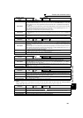
Operation Panel
Indication
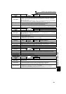
E.OP1
E.OP2
FR-PU04
FR-PU07(-01)
Option 1 Fault
Option 2 Fault
Name
Communication option fault
Description Stops the inverter output when a communication line fault occurs in the communication option.
Check point
· Check for a wrong option function setting and operation.
· Check that the plug-in option is plugged into the connector securely.
· Check for a break in the communication cable.
· Check that the terminating resistor is fitted properly.
Corrective action
· Check the option function setting, etc.
· Connect the plug-in option securely.
· Check the connection of communication cable.
... Specifications differ according to the date assembled. Refer to page 400 to check the SERIAL number.