


143
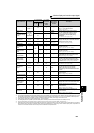
Monitor display and monitor output signal
4
PARAMETERS
*1 Frequency setting to output terminal status on the PU main monitor are selected by "other monitor selection" of the parameter unit (FR-PU04
, FR-PU07
).
*2 The cumulative energization time and actual operation time are accumulated from 0 to 65535 hours, then cleared, and accumulated again from 0. When
the operation panel (FR-DU07) is used, the time is displayed up to 65.53 (65530h) in the indication of 1h = 0.001, and thereafter, it is added up from 0.
*3 The actual operation time is not added up if the cumulative operation time before power supply-OFF is less than 1h.
*4 When using the parameter unit (FR-PU04/FR-PU07), "kW" is displayed.
*5 The setting depends on capacities. (FR-F720-02330 (FR-F740-01160) or less/FR-F720-03160 (FR-F740-01800) or more)
*6 Since the panel display of the operation panel is 4 digits in length, the monitor value of more than "9999" is displayed as "----".
*7 When the output current is less than the specified current level (5% of the rated inverter current), the output current is monitored as 0A. Therefore,
the monitored value of an output current and output power may be displayed as "0" when using a much smaller-capacity motor compared to the
inverter or in other instances that cause the output current to fall below the specified value.
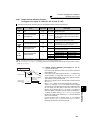
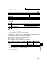
Cumulative power
*6
0.01kWh/
0.1kWh
*4, *5
25
×
⎯
Displays the cumulative power amount
according to the output power monitor
Use Pr. 170 to clear the value.
(Refer to page 146.)
Power saving
effect Variable
according
to
parameters
50 50
Inverter
capacity
Displays energy saving effect monitor
You can change the monitor to power
saving, power saving average value,
charge display and % display using
parameters.
(For details, refer to page 165.)
Cumulative saving
power
*6
51
×
⎯
PID set point 0.1% 52 52
100%/
C42 or C44
Displays the set point, measured value and
deviation during PID control
(For details, refer to page 269.)
PID measured
value
0.1% 53 53
100%/
C42 or C44
PID deviation 0.1% 54
×
⎯
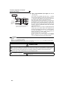
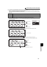
Input terminal
status
⎯
55
*1
×
⎯
Displays ON/OFF status of the input
terminal on the PU
(Refer to page 145 for DU display)
Output terminal
status
⎯
*1
×
⎯
Displays ON/OFF status of the output
terminal on the PU
(Refer to page 145 for DU display)
Option input
terminal status
⎯
56
××
⎯
Displays ON/OFF status of the input terminal
of the digital input option (FR-A7AX) on the
DU (Refer to page 145 for details)
Option output
terminal status
⎯
57
××
⎯
Displays ON/OFF status of the output
terminal of the digital output option (FR-
A7AY) and relay output option (FR-A7AR)
on the DU (Refer to page 145 for details)
PID measured
value 2
0.1% 67 67
100%/
C42 or C44
Displays the measured value
(For details, refer to page 269.)
PLC function
output
0.1%
×
70 100%
Desired values can be output from terminal
CA and AM using the PLC function.
Refer to the FR-F700 PLC function
programming manual for details of the PLC
function.
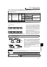
BACnet reception
status
181
× ⎯
Displays the reception status of BACnet
communication
(Refer to page 247 for details)
BACnet token pass
counter
182
×
⎯
Displays the count of received token
BACnet valid
APDU counter
183
×
⎯
Displays the count of valid APDU detection
BACnet
communication
error counter
184
×
⎯
Displays the count of communication error
Terminal CA output
level
⎯
85
85
(Pr. 54 only)
20mA
Displays actual output current level of
terminal CA which is controlled by BACnet
communication
(Refer to page 247 for details)
Terminal AM
output level
⎯
86
86
(Pr. 158 only)
10V
Displays actual output voltage level of
terminal AM which is controlled by BACnet
communication
(Refer to page 247 for details)
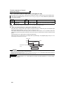
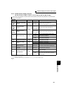
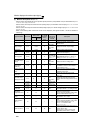
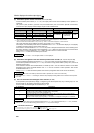
Types of Monitor Increments
Pr. 52 Parameter
Setting Value
Pr. 54 (CA)
Pr. 158 (AM)
Parameter
Setting
Value
Full-scale
value of the
terminal CA
and AM
Description
DU LED
PU main
monitor