


182
Frequency setting by analog input (terminal 1, 2, 4)
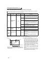
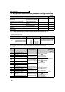
4.16.5 4mA input check of current input (Pr. 573, Pr. 777, Pr. 778)
The above parameters can be set when Pr. 160 User group read selection = "0". (Refer to page 190.)
....Specifications differ according to the date assembled. Refer to page 400 to check the SERIAL number.
When inputting 4 to 20mA current to terminal 2 or terminal 4, decrease in analog current input is detected to
enable continuous operation even if input has decreased.
Parameter
Number
Name Initial Value
Setting
Range
Description
573
4mA input check
selection
9999
1
When the current input drops to or below 2mA, the LF
signal is output and inverter continues operation at the
frequency (average value) just before current reaches
2mA.
2
When the analog input current drops to or below 2mA,
the fault (E.LCI) is output and the inverter output is
shutoff.
3
When the analog input current drops to or below 2mA,
the alarm signal (LF) is output, and the fault (E.LCI) is
output after deceleration to a stop. When the current
rises to or above 3mA during the deceleration, the
motor accelerates again to the set point and resumes
normal operation.
4
When the analog input current drops to or below 2mA,
the alarm signal (LF) is output and the inverter
continues operation at the Pr. 777 setting.
9999 4mA input is not checked.
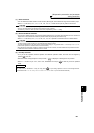
777
4mA input fault
operation
frequency
9999
0 to 400Hz
Set the frequency to continue the operation when the
analog input current drops to or below 2mA while Pr. 573
="4."
9999 4mA input is not checked while Pr. 573 = "4."
778
Current input check
filter
0 0 to 10s
Detection for an analog input current drop is performed
for the time period of Pr. 778 while the analog input
current ≤ 2mA.
Detection for an analog input current drop is cancelled
for the time period of Pr. 778 while the analog input
current > 3mA.
Pr. 778 =0: Immediately detected or the detection is
cancelled.
* When Pr.573 = "1", input decrease is detected (LF signal output) even if
the analog input value to bias frequency of terminal 2 or terminal 4 is set
to 2mA or less using C2 (Pr. 902) or C5 (Pr. 904) and the value is not as
bias frequency settings.
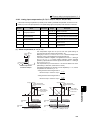
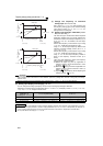
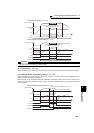
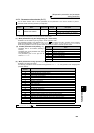
(1) Operation continuation (Pr. 573 = "1")
⋅
When the input current of terminal 4 (terminal 2) falls
2mA or below, output alarm output signal (LF) is output.
⋅
When the current falls below 2mA, the output
frequency (average value) before detection is retained
and operation at the retained frequency continues.
⋅ When the current input increases above 3mA, the
LF signal output is turned OFF and the inverter
operates according to the current input.
⋅
For the LF signal, set "98 (positive logic) or 198
(negative logic)" in
Pr. 190 to Pr. 196 (output terminal
function selection)
and assign functions to the output
terminal.
⋅ Since turning OFF the start command clears the
retained frequency, the inverter does not operate at
the retained frequency even if restarted.
4mA2mA
60Hz
20mA
Set frequency
Analog inpu
t
When C3(C6) = 0%
Normal use range
Current input
decrease detection
*