


110
Selection and protection of a motor
(6) PTC thermistor input (PTC signal)
Built-in PTC thermistor of the motor can be input to the PTC signal (AU terminal).
⋅ For the terminal used for PTC signal input, assign the function by setting "63" in Pr. 184 AU terminal function selection
and also set the AU/PTC switchover switch to the PTC terminal function. (The initial setting is the AU terminal
function.)
⋅ If a motor overheat state is detected for more than 10s according to the input from the PTC thermistor, the inverter
shuts off the output and outputs the PTC thermal fault signal (E.PTC).
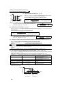
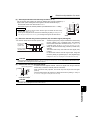
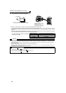
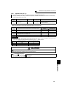
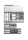
PTC thermistor input connection example
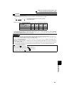
⋅ The input specifications of the PTC thermistor
are shown on the right.
Motor Temperature PTC Thermistor Resistance Value (Ω)
Normal 0 to 500
Boundary 500 to 4k
Overheat 4k or higher
CAUTION
⋅ When the PTC signal was not assigned to Pr. 184 and the AU/PTC switchover switch was set to the PTC terminal function, the
function assigned to the AU terminal is always OFF. Reversely, when the PTC signal was assigned to Pr. 184 and the AU/PTC
switchover switch was set to the AU terminal function, a PTC thermal error (E.PTC) occurs since the function is always in a
motor overheat state.
⋅ When you want to input a current, assign the AU signal to the other signal.
⋅ Changing the terminal assignment using Pr. 178 to Pr. 189 (input terminal function selection) may affect the other functions. Set
parameters after confirming the function of each terminal.
♦ Parameters referred to ♦
Pr. 71 Applied motor Refer to page 111
Pr. 72 PWM frequency selection Refer to page 169
Pr. 178 to Pr. 189 (Input terminal function selection) Refer to page 122
Pr. 190 to Pr. 196 (Output terminal function selection) Refer to page 128
Specifications of the AU terminal Refer to page 27
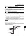
Inverter
U
AU
PTC
V
W
AU(PTC)
Moto
r
SD
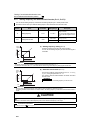
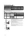
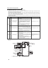
Inverter
AU/PTC switchover switch
AU
PTC
Factory-set to "AU".
Set to the "PTC" position to
validate the PTC signal input.