


142
Monitor display and monitor output signal
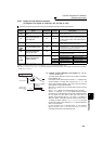
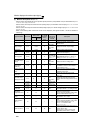
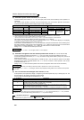
(1) Monitor description list (Pr. 52)
⋅ Set the monitor to be displayed on the operation panel (FR-DU07) and parameter unit (FR-PU04/FR-PU07) in Pr.
52 DU/PU main display data selection.
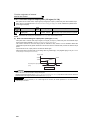
⋅ Set the monitor to be output to the terminal CA (analog output (0 to 20mADC current output)) in Pr. 54 CA terminal
function selection.
⋅ Set the monitor to be output to the terminal AM (analog output (0 to 10VDC voltage output)) in Pr. 158 AM terminal
function selection.
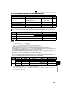
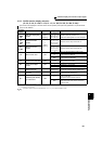
⋅ Refer to the following table and set the monitor to be displayed. (The signals marked × cannot be selected for
monitoring)
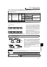
Types of Monitor Increments
Pr. 52 Parameter
Setting Value
Pr. 54 (CA)
Pr. 158 (AM)
Parameter
Setting
Value
Full-scale
value of the
terminal CA
and AM
Description
DU LED
PU main
monitor
Output frequency 0.01Hz 0/100 1
Pr. 55
Displays the inverter output frequency
Output current
*7
0.01A/0.1A
*5
0/100 2
Pr. 56
Displays the inverter output current
effective value
Output voltage 0.1V 0/100 3
200V class:
400V
400V class:
800V
Displays the inverter output voltage
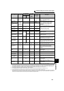
Fault display
⎯
0/100
×
⎯
Displays 8 past faults individually
Frequency setting
value
0.01Hz 5
*1
5
Pr. 55
Displays the set frequency
Running speed 1(r/min) 6
*1
6
The value
converted with
the Pr. 37 value
from Pr. 55
Displays the motor speed
(The display
differs depending on the
Pr. 37
and
Pr. 144
settings.)
(For details, refer to page 139 .)
Converter output
voltage
0.1V 8
*1
8
200V class:
400V
400V class:
800V
Displays the DC bus voltage value
Regenerative
brake duty
0.1% 9
*1
9
Pr. 70
Brake duty set in Pr. 30 and Pr. 70 (Setting
is available for the FR-F720-03160 (FR-
F740-01800) or more)
Electronic thermal
relay function load
factor
0.1% 10
*1
10 100%
Displays the motor thermal cumulative
value on the assumption that the thermal
operation level is 100%.
Output current
peak value
0.01A/0.1A
*5
11
*1
11
Pr. 56
Retains the peak value of the output
current monitor and displays (clears at
every start)
Converter output
voltage peak value
0.1V 12
*1
12
200V class:
400V
400V class:
800V
Retains the peak value of the DC bus
voltage value and displays (clears at every
start)
Input power
0.01kW/
0.1kW
*5
13
*1
13
Rated inverter
power × 2
Displays power of the inverter input side
Output power
*7
0.01kW/
0.1kW
*5
14
*1
14
Rated inverter
power
× 2
Displays power of the inverter output side
Load meter
0.1%
17 17 100%
Displays the torque current in % on the
assumption that the Pr. 56 setting is 100%
Cumulative
energization time
*2
1h 20
×
⎯
Displays the cumulative energization time
since the inverter shipment
You can check the numbers of the monitor
value exceeded 65535h with Pr. 563.
Reference voltage
output
⎯⎯
21
⎯
Terminal CA: 20mA is output
Terminal AM: 10V is output
Actual operation
time
*2*3
1h 23
×
⎯
Displays the cumulative inverter running
time.
You can check the numbers of the monitor
value exceeded 65535h with Pr. 564.
Use Pr. 171 to clear the value.
(Refer to page 146 .)
Motor load factor 0.1% 24 24 200%
Displays the output current value in % on
the assumption that the rated inverter
current value is 100%.
Monitor value = output current monitor
value/rated inverter current
× 100 [%]