


25
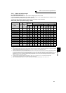
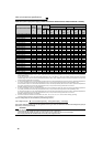
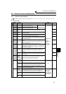
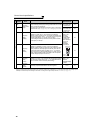
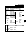
Main circuit terminal specifications
2
WIRING
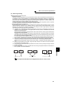
2.2.4 When connecting the control circuit and the main circuit separately to the
power supply
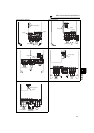
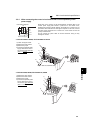
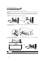
• FR-F720-00046 to 00250, FR-F740-00023 to 00126
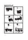
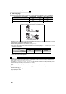
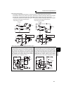
• FR-F720-00340, 00490, FR-F740-00170, 00250
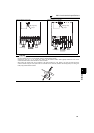
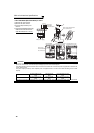
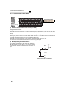
<Connection diagram> When fault occurs, opening of the electromagnetic contactor (MC) on the
inverter power supply side results in power loss in the control circuit,
disabling the fault output signal retention. Terminals R1/L11 and S1/L21 are
provided for when retention of a fault signal is required. In this case, connect
the power supply terminals R1/L11 and S1/L21 of the control circuit to the
primary side of the MC.
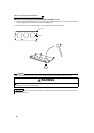
Do not connect the power cable to incorrect terminals. Doing so may
damage the inverter.
1)Loosen the upper screws.
2)Remove the lower screws.
3)Remove the jumper
4)Connect the separate power
supply cable for the control
circuit to the lower terminals
(R1/L11, S1/L21).
1)Remove the upper screws.
2)Remove the lower screws.
3)Remove the jumper.
4)Connect the separate power
supply cable for the control
circuit to the upper terminals
(R1/L11, S1/L21).
Inverter
MC
R/L1
S/L2
T/L3
R1/L11
S1/L21
Remove the jumper
Main circuit terminal block
R1/L11
S1/L21
3)
1)
2)
4)
S/L2
T/L3
R1/L11
S1/L21
R/L1
3)
4)
1)
2)
Main circuit
terminal block
S1/L21
R1/L11
S/
L2
T/
L3
R/
L1
R1/L11
S1/L21