


295
Special operation and frequency control
4
PARAMETERS
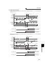
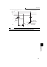
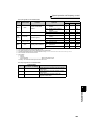
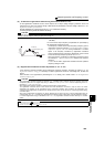
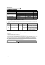
⋅ The input signals are as indicated below.
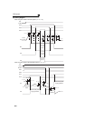
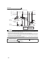
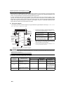
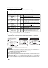
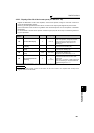
⋅ The output signals are as indicated below.
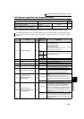
Signal Terminal Used Function Operation
MC Operation
*6
MC1
*5
MC2 MC3
MRS MRS
Operation enable/disable
selection
*1
ON .....Bypass-inverter operation
enabled
⎯⎯
OFF ... Bypass-inverter operation
disabled
×
No
change
CS CS Inverter/bypass
*2
ON......Inverter operation
×
OFF ... Bypass operation
×
STF
(STR)
STF(STR)
Inverter operation command
(Invalid for bypass)
*3
ON......Forward rotation (reverse
rotation)
×
OFF....Stop
×
OH
Set "7" in any of
Pr. 180 to Pr. 189.
External thermal relay input
ON .....Motor normal
⎯⎯
OFF....Motor abnormal
×××
RES RES
Operating status initialization
*4
ON......Initialization
No
change
×
No
change
OFF....Normal operation
⎯⎯
*1 Unless the MRS signal is turned ON, neither bypass operation nor inverter operation can be performed.
*2 The CS signal functions only when the MRS signal is ON.
*3 STF (STR) functions only when both the MRS signal and CS signal are ON.
*4 The RES signal enables reset input acceptance selection using Pr. 75 Reset selection/disconnected PU detection/PU stop selection.
*5 MC1 turns OFF when an inverter fault occurs.
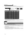
*6 MC operation
: MC-ON
× : MC-OFF
⎯ : Inverter operation...................................................MC2 is OFF and MC3 is ON
Bypass operation ...................................................MC2 is ON and MC3 is OFF
No change : The status before the signal turns ON or OFF is held.
Signal
Terminal Used
(Pr. 190 to Pr. 196 setting)
Description
MC1 17
Control signal output of inverter input side magnetic
contactor MC1
MC2 18
Control signal output of bypass operation magnetic
contactor MC2
MC3 19
Control signal output of inverter output side
magnetic contactor MC3