


244
Communication operation and setting
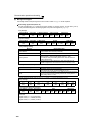
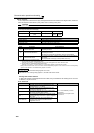
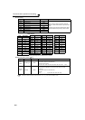
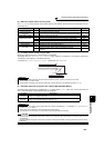
Faults history
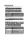
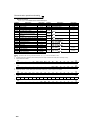
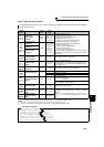
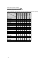
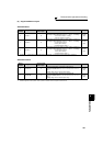
Fault code list
* Refer to the FR-F700 PLC function programming manual for details of the PLC function.
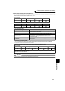
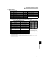
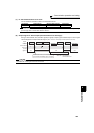
Model information monitor
... Specifications differ according to the date assembled. Refer to page 400 to check the SERIAL number.
Register Definition Read/Write Remarks
40501 Fault history 1 Read/write
Being 2 bytes in length, the data is stored as
"H00". Refer to the lowest 1 byte for the fault
code.
Performing write using the register 40501 batch-
clears the faults history. Set any value as data.
40502 Fault history 2 Read
40503 Fault history 3 Read
40504 Fault history 4 Read
40505 Fault history 5 Read
40506 Fault history 6 Read
40507 Fault history 7 Read
40508 Fault history 8 Read
Register Definition Read/Write Remarks
44001 to
44010
Inverter type Read
Reading inverter type in ASCII code.
"H20" (blank code) is set for blank area
Example of FR-F720-NA
H46, H52, H2D, H46, H37, H32, H30, H2D, H4E, H41, H20.......H20
44011 to
44013
Capacity Read
Reading inverter capacity in ASCII code.
Data is read in increments of 0.1kW, and rounds down to 0.01kW
increments
"H20" (blank code) is set for blank area
Example
0.75K............... " 7" (H20, H20, H20, H20, H20, H37)
Data Description
H00 No fault
H10 OC1
H11 OC2
H12 OC3
H20 OV1
H21 OV2
H22 OV3
H30 THT
H31 THM
H40 FIN
H50 IPF
H51 UVT
H52 ILF
H60 OLT
H70 BE
H80 GF
H81 LF
H90 OHT
H91 PTC
HA0 OPT
HA1 OP1
HA2 OP2
HA4 E.16 *
HA5 E.17 *
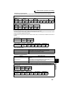
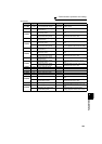
Data Description
HA6 E.18 *
HA7 E.19 *
HA8 E.20 *
HB0 PE
HB1 PUE
HB2 RET
HB3 PE2
HC0 CPU
HC1 CTE
HC2 P24
HC4 CDO
HC5 IOH
Data Description
HC6 SER
HC7 AIE
HE4 LCI
HE5 PCH
HE6 PID
HF1 E.1
HF2 E.2
HF5 E.5
HF6 E.6
HF7 E.7
HFD E.13
Data Description