


I
CONTENTS
CONTENTS
1 OUTLINE 1
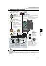
1.1 Product checking and parts identification ........................................................ 2
1.2 Inverter and peripheral devices.......................................................................... 3
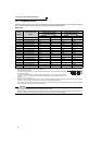
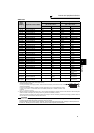
1.2.1 Peripheral devices ..................................................................................................................... 4
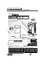
1.3 Method of removal and reinstallation of the front cover ................................. 6
1.4 Installation of the inverter and enclosure design............................................. 8
1.4.1 Inverter installation environment................................................................................................ 8
1.4.2 Cooling system types for inverter enclosure............................................................................ 10
1.4.3 Inverter placement................................................................................................................... 10
2 WIRING 13
2.1 Wiring.................................................................................................................. 14
2.1.1 Terminal connection diagram .................................................................................................. 14
2.1.2 EMC filter................................................................................................................................. 15
2.2 Main circuit terminal specifications................................................................. 16
2.2.1 Specification of main circuit terminal ....................................................................................... 16
2.2.2 Terminal arrangement of the main circuit terminal, power supply and the motor wiring ......... 16
2.2.3 Cables and wiring length ......................................................................................................... 21
2.2.4 When connecting the control circuit and the main circuit separately to the power supply....... 25
2.3 Control circuit specifications ........................................................................... 27
2.3.1 Control circuit terminals ........................................................................................................... 27
2.3.2 Changing the control logic ....................................................................................................... 30
2.3.3 Control circuit terminal layout .................................................................................................. 32
2.3.4 Wiring instructions ................................................................................................................... 33
2.3.5 Mounting the operation panel (FR-DU07) on the enclosure surface ....................................... 34
2.3.6 RS-485 terminal block ............................................................................................................. 35
2.3.7 Communication operation........................................................................................................ 35
2.4 Connection of stand-alone option units.......................................................... 36
2.4.1 Connection of the brake unit (FR-BU2) ................................................................................... 36
2.4.2 Connection of the brake unit (FR-BU/MT-BU5)....................................................................... 38
2.4.3 Connection of the brake unit (BU type) ................................................................................... 40
2.4.4 Connection of the high power factor converter (FR-HC/MT-HC)............................................. 40
2.4.5 Connection of the power regeneration common converter (FR-CV)
(FR-F720-02330 (FR-F740-01160) or less) ............................................................................ 42
2.4.6 Connection of the power regeneration converter (MT-RC)
(FR-F720-03160 (FR-F740-01800) or more)........................................................................... 43
2.4.7 Connection of the power factor improving DC reactor (FR-HEL) ............................................ 44
3 PRECAUTIONS FOR USE OF THE INVERTER 45