


340
Causes and corrective actions
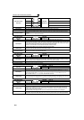
Operation Panel
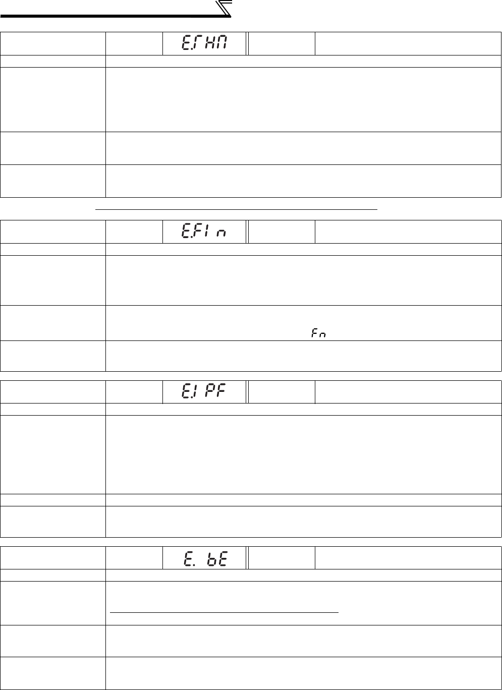
Indication
E.THM
FR-PU04
FR-PU07(-01)
Motor Ovrload
Name
Motor overload trip (electronic thermal relay function) *1
Description
The electronic thermal relay function in the inverter detects motor overheat due to overload or reduced
cooling capability during constant-speed operation and pre-alarm (TH display) is output when the
integrated value reaches 85% of the Pr. 9 Electronic thermal O/L relay setting and the protection circuit is
activated to stop the inverter output when the integrated value reaches the specified value. When
running a special motor such as a multi-pole motor or multiple motors, provide a thermal relay on the
inverter output side since such motor(s) cannot be protected by the electronic thermal relay function.
Check point
· Check the motor for use under overload.
· Check that the setting of Pr. 71 Applied motor for motor selection is correct. (Refer to page 111.)
· Check that stall prevention operation setting is correct.
Corrective action
· Reduce the load weight.
· For a constant-torque motor, set the constant-torque motor in Pr. 71 Applied motor.
· Check that stall prevention operation setting is correct. (Refer to page 81.)
*1 Resetting the inverter initializes the internal thermal integrated data of the electronic thermal relay function.
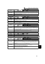
Operation Panel
Indication
E.FIN
FR-PU04
FR-PU07(-01)
H/Sink O/Temp
Name
Heatsink overheat
Description
If the heatsink overheats, the temperature sensor is actuated to stop the inverter output.
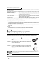
The FIN signal can be output when the temperature becomes approximately 85% of the heatsink
overheat protection operation temperature.
For the terminal used for the FIN signal output, assign the function by setting "26" (positive logic) or
"126" (negative logic) in any of Pr. 190 to Pr. 196 (output terminal function selection). (Refer to page 128)
Check point
· Check for too high surrounding air temperature.
· Check for heatsink clogging.
· Check that the cooling fan is stopped. (Check that is displayed on the operation panel.)
Corrective action
· Set the surrounding air temperature to within the specifications.
· Clean the heatsink.
· Replace the cooling fan.
Operation Panel
Indication
E.IPF
FR-PU04
FR-PU07(-01)
Inst. Pwr. Loss
Name
Instantaneous power failure
Description
If a power failure occurs for longer than 15ms (this also applies to inverter input shut-off), the
instantaneous power failure protective function is activated to trip the inverter in order to prevent the
control circuit from malfunctioning. If a power failure persists for longer than 100ms, the fault output is not
provided, and the inverter restarts if the start signal is ON upon power restoration. (The inverter continues
operating if an instantaneous power failure is within 15ms.) In some operating status (load magnitude,
acceleration/deceleration time setting, etc.), overcurrent or other protection may be activated upon power
restoration.
When instantaneous power failure protection is activated, the IPF signal is output.
(
Refer to page 152
)
Check point
Find the cause of instantaneous power failure occurrence.
Corrective action
· Remedy the instantaneous power failure.
· Prepare a backup power supply for instantaneous power failure.
· Set the function of automatic restart after instantaneous power failure (Pr. 57). (Refer to page 152.)
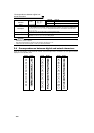
Operation Panel
Indication
E.BE
FR-PU04
FR-PU07(-01)
Br. Cct. Fault
Name
Brake transistor alarm detection/internal circuit fault
Description
This function stops the inverter output if a fault occurs in the brake circuit, e.g. damaged brake
transistors when using functions of the FR-F720-03160 (FR-F740-01800) or more.
In this case, the inverter must be powered OFF immediately.
For the FR-F720-02330 (FR-F740-01160) or less, it appears when an internal circuit error occurred.
Check point
· Reduce the load inertia.
· Check that the frequency of using the brake is proper.
· Check that the brake resistor selected is correct.
Corrective action
For the FR-F720-03160 (FR-F740-01800) or more, when the protective function is activated even if the
above measures are taken, replace the brake unit with a new one.
For the FR-F720-02330 (FR-F740-01160) or less, replace the inverter.