


270
PID control
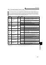
(10) Calibration example
(A detector of 4mA at 0°C and 20mA at 50°C is used to adjust the room temperature to 25°C under PID control.
The set point is given to across inverter terminals 2 and 5 (0 to 5V).)
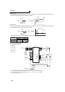
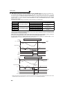
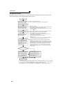
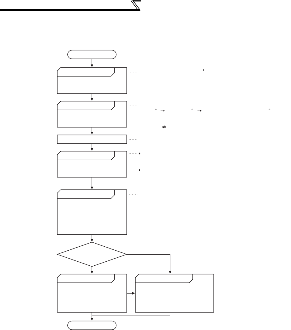
Start
Determination of set point
Conversion of set point into %
Make calibration.
Setting of set point
Operation
Is the set point stable?
Parameter adjustment Parameter optimization
Adjustment end
Yes
No
When the parameter unit is used for operation, input the set point to
Pr. 133.
When performing operation, first set the proportional band (Pr. 129) to a
slightly larger value, the integral time (Pr. 130) to a slightly longer time, and
the differential time (Pr. 134) to "9999" (no function), and while looking at
the system operation, decrease the proportional band (Pr. 129) and
increase the integral time (Pr. 130). For slow response system where a
deadband exists, differential control (Pr. 134) should be turned ON and
increased slowly.
Determine the set point of
what is desired to be adjusted.
Calculate the ratio of the set
point to the detector output.
Input the set point.
To stabilize the measured value,
change the proportional band (Pr.
129) to a larger value, the integral
time (Pr. 130) to a slightly longer
time, and the differential time (Pr.
134) to a slightly shorter time.
While the measured value is stable
throughout the operation status, the
proportional band (Pr. 129) may be
decreased, the integral time (Pr. 130)
decreased, and the differential time
(Pr. 134) increased.
Set the proportional band (Pr.
129) to a slightly larger value,
the integral time (Pr. 130) to a
slightly longer time, and the
differential time (Pr. 134) to
"9999" (no function), and turn
ON the start signal.
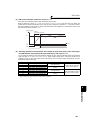
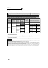
Make the following calibration* when the target setting input (0 to 5V) and
detector output (4 to 20mA, 0 to 100%) must be calibrated.
Set the room temperature to 25 C.
Set Pr. 128 and turn ON the X14 signal to enable PID control.
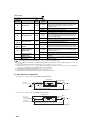
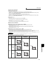
Detector specifications
When 0 C 4mA and 50 C 20mA are used, the set point 25 C is 50%
on the assumption that 4mA is 0% and 20mA is 100%.
(Converting set point to % is unnecessary when both of C42(Pr.934) and
C44(Pr.935) "9999".)
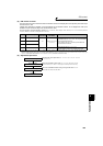
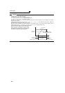
When setting 50% as the set point with voltage input
In the specification of terminal 2, 0V converts to 0% and 5V to 100%.
Thus, set 2.5V for 50% to terminal 2.
When setting 50% as the set point with parameter
Set "50" to Pr.133.
(When both of C42(Pr.934) and C44(Pr.935) are set other than "9999", set
"25" as the set point (no % conversion) directly to the Pr.133.)
* When calibration is required
To perform calibration for detector output and set point input, set calibration parameters Pr. 902 and Pr. 903 (terminal
2), or Pr. 904 and Pr. 905 (terminal 4). However, use Pr. 934 and Pr. 935 instead of Pr. 904 and Pr. 905 when both of C42
(Pr. 934) and C44(Pr. 935) ≠ "9999". Make calibration in the PU mode during an inverter stop.
(For the details of Pr. 902 to Pr. 905, refer to page 177. For the details of Pr. 934 and Pr. 935, refer to page 271.)