


302
Useful functions
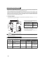
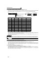
(1) Life alarm display and signal output (Y90 signal, Pr. 255)
⋅ Whether any of the control circuit capacitor, main circuit capacitor, cooling fan and inrush current limit circuit has reached
the life alarm output level or not can be checked by Pr. 255 Life alarm status display and life alarm signal (Y90).
⋅ The life alarm signal (Y90) turns ON when any of the control circuit capacitor, main circuit capacitor, cooling fan and
inrush current limit circuit reaches the life alarm output level.
⋅ For the terminal used for the Y90 signal, set "90" (positive logic) or "190" (negative logic) in any of Pr. 190 to Pr. 196
(output terminal function selection).
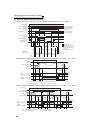
(2) Life display of the inrush current limit circuit (Pr. 256)
⋅ The life of the inrush current limit circuit (relay, contactor and inrush resistor) is displayed in Pr. 259.
⋅ The number of contact (relay, contactor, thyristor) ON times is counted, and it is counted down from 100% (0 times)
every 1%/10,000 times. As soon as 10% (900,000 times) is reached, Pr. 255 bit 3 is turned ON and also an alarm is
output to the Y90 signal.
(3) Control circuit capacitor life display (Pr. 257)
⋅ The deterioration degree of the control circuit capacitor is displayed in Pr. 257 as a life.
⋅ In the operating status, the control circuit capacitor life is calculated from the energization time and temperature,
and is counted down from 100%. As soon as the control circuit capacitor life falls below 10%, Pr. 255 bit 0 is turned
ON and also an alarm is output to the Y90 signal.
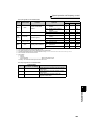
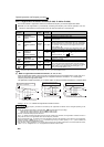
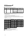
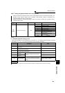
Pr. 255
(decimal)
Bit
(binary)
Inrush
Current Limit
Circuit Life
Cooling
Fan Life
Main Circuit
Capacitor Life
Control Circuit
Capacitor Life
15 1111
14 1110 ×
13 1101 ×
12 1100 ××
11 1011 ×
10 1010 × ×
9 1001 ××
8 1000 ×× ×
7 0111 ×
60110 × ×
5 0101 × ×
4 0100 × ××
30011 ××
2 0010 ×× ×
1 0001 ×× ×
0 0000 ×× × ×
: With warnings, ×: Without warnings
REMARKS
⋅ The digital output option (FR-A7AY, FR-A7AR, FR-A7NC) allows the control circuit capacitor life signal (Y86), main circuit
capacitor life signal (Y87), cooling fan life signal (Y88) and inrush current limit circuit life signal (Y89) to be output individually.
CAUTION
⋅ Changing the terminal assignment using Pr. 190 to Pr. 196 (output terminal function selection) may affect the other functions.
Please set parameters after confirming the function of each terminal.
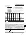
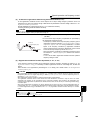
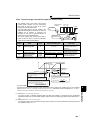
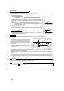
0 0 0 0 0 0 0 0 0 0 0 0 1 0 0
bit0 Control circuit capacitor life
1
15bit 7 0
bit1 Main circuit capacitor life
bit2 Cooling fan life
bit3 Inrush current limit circuit life
• Pr.255 read
Bit image is displayed
in decimal
• Pr.255 setting read