


171
Frequency setting by analog input (terminal 1, 2, 4)
4
PARAMETERS
4.16 Frequency setting by analog input (terminal 1, 2, 4)
4.16.1 Analog input selection (Pr. 73, Pr. 267)
(1) Selection of analog input selection
⋅ For the terminals 2, 4 used for analog input, voltage input (0 to 5V, 0 to 10V) or current input (4 to 20mA) can be
selected.
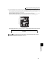
Change parameters (Pr.73, Pr.267) and a voltage/current input switch (switch 1, 2) to change input specifications.
⋅ Rated specifications of terminal 2 and 4 change according to the voltage/current input switch setting.
Voltage input: Input resistance 10kΩ ± 1kΩ, Maximum permissible voltage 20VDC
Current input: Input resistance 245Ω ± 5Ω, Maximum permissible current 30mA
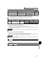
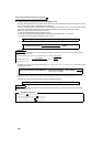
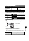
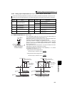
Purpose Parameter that must be Set Refer to Page
Selection of voltage/current input
(terminal 1, 2, 4) Perform forward/
reverse rotation by analog input.
Analog input selection Pr. 73, Pr. 267 171
Adjust the main speed by analog
auxiliary input.
Analog auxiliary input and
compensation (added compensation
and override function)
Pr. 73, Pr. 242, Pr. 243,
Pr. 252, Pr. 253
175
Noise elimination at the analog input Input filter Pr. 74 176
Adjustment (calibration) of analog
input frequency and voltage (current)
Bias and gain of frequency setting
voltage (current)
Pr. 125, Pr. 126, Pr. 241,
C2 to C7 (Pr. 902 to Pr. 905)
177
You can select the function that switches between forward rotation and reverse rotation according to the analog
input terminal selection specifications, the override function and the input signal polarity.
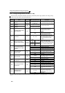
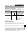
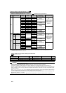
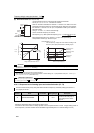
Parameter
Number
Name
Initial
Value
Setting
Range
Description
Voltage/current
input switch
73 Analog input selection 1
0 to 5,
10 to 15
Switch 2 - OFF
(initial status)
You can select the input specifications of terminal 2 (0
to 5V, 0 to 10V, 0 to 20mA) and input specifications of
terminal 1 (0 to ±5V, 0 to ±10V).
Override and reversible operation can be selected.
6, 7,
16, 17
Switch 2 - ON
267
Terminal 4 input
selection
0
0
Switch 1 - ON
(initial status)
Terminal 4 input 4 to 20mA
1
Switch 1 - OFF
Terminal 4 input 0 to 5V
2 Terminal 4 input 0 to 10V
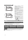
The above parameters can be set when Pr. 160 User group read selection = "0". (Refer to page 190)
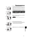
Switch 1:Terminal 4 input
ON: Current input (initial status)
OFF: Voltage input
Switch 2: Terminal 2 input
ON: Current input
OFF: Voltage input (initial status)
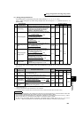
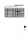
CAUTION
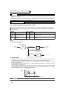
⋅ Set Pr. 73, Pr. 267, and a voltage/current input switch correctly, then input an analog signal in accordance with
the setting. Incorrect setting as in the table below could cause component damage. Incorrect settings other than
below can cause abnormal operation.
Voltage/current
input switch
2
4
Switch 1
Switch 2
Setting Causing Component Damage
Operation
Switch setting Terminal input
ON
(Current input)
Voltage input
This could cause component damage to the analog signal output circuit of signal output
devices. (electrical load in the analog signal output circuit of signal output devices increases)
OFF
(Voltage input)
Current input
This could cause component damage of the inverter signal input circuit. (output
power in the analog signal output circuit of signal output devices increases)