


262
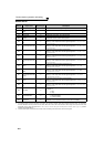
PID control
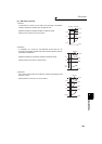
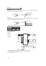
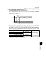
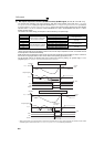
(1) PID control basic configuration
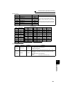
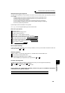
⋅ Pr. 128 (Pr. 753) = "10, 11, 110, 111" (Deviation value signal input)
⋅ Pr. 128 (Pr. 753) = "20, 21, 120, 121" (Measured value input)
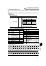
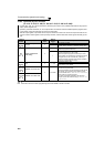
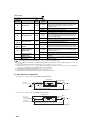
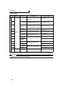
132 PID lower limit 9999
0 to 100%
*3
Set the lower limit value. If the measured value falls below the
setting range, the FDN signal is output. The maximum input
(20mA/5V/10V) of the measured value (terminal 4) is
equivalent to 100%.
9999 No function
133
*1 PID action set point 9999
0 to 100%
*3 Used to set the set point for PID control.
9999 Terminal 2 input is the set point.
134 *1 PID differential time 9999
0.01 to
10.00s
When deviation lamp is input, time (Td) is the time required to
provide the manipulated variable of only the proportional (P)
action. As the differential time increases, greater response is
made to a deviation change.
9999 No differential control.
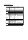
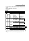
553
PID deviation limit 9999
0 to 100.0%
*3
Y48 signal is output when the absolute value of deviation
amount exceeds the deviation limit value.
9999 No function
554
PID signal operation
selection
0
0 to 3,
10 to 13
Select the operation to be performed at the detection of upper,
lower, and deviation limit for the measured value input. The
operation for PID output suspension function can be selected.
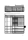
575
Output interruption
detection time
1s
0 to 3600s
The inverter stops operation if the output frequency after PID
operation remains at less than the Pr. 576 setting for longer
than the time set in Pr. 575.
9999 Without output interruption function
576
Output interruption
detection level
0Hz 0 to 400Hz
Set the frequency at which the output interruption processing is
performed.
577
Output interruption
cancel level
1000% 900 to 1100%
Set the level (Pr. 577 minus 1000%) to release the PID output
interruption function.
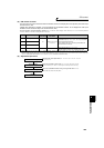
The above parameters can be set when Pr. 160 User group read selection = "0". (Refer to page 190)
... Specifications differ according to the date assembled. Refer to page 400 to check the SERIAL number.
*1 The above parameters allow its setting to be changed during operation in any operation mode even if "0" (initial value) is set in Pr. 77 Parameter
write selection.
*2 PID control is available without turning X14 signal ON when Pr.128 = "50, 51, 60, 61, 110, 111, 120, 120".
*3 Setting values of Pr.131 to Pr.133, Pr.553, Pr.577 are without unit when "9999" is set to both of C42(Pr.934) and C44(Pr.935). (The values set to
Pr.553 and Pr.577 indicate deviation range whether the unit is % or is not indicated.)
*4 Input specification for the terminals are determined by Pr.73 Analog input selection.
*5 Input specification for the terminal is determined by Pr.267 Terminal 4 input selection.
*6 Refer to the FR-F700 PLC function programming manual for details of the PLC function.
Parameter
Number
Name
Initial
Value
Setting
Range
Description
+
-
M
Deviation signal
Feedback signal (measured value)
Ti S
1
1+
+Td S
Kp
PID operation
To outside
Set point
Inverter circuit
Motor
Terminal 1
0 to 10VDC
(0 to 5V)
Kp: Proportionality constant Ti: Integral time S: Operator Td: Differential time
Manipulated
variable
*
+
-
M
Ti S
Kp 1+ +Td S
1
PID operation
Pr. 133 or
terminal 2
Set point
Inverter circuit
Motor
Feedback signal (measured value)
Terminal 4
Kp: Proportionality constant Ti: Integral time S: Operator Td: Differential time
Manipulated
variable
0 to 5VDC
(0 to 10V, 4 to 20mA)
4 to 20mADC (0 to 5V, 0 to 10V)
*1
*2