


294
Special operation and frequency control
⋅ When the motor is operated at 60Hz (or 50Hz), more efficient operation can be performed by the commercial power
supply than by the inverter. When the motor cannot be stopped for a long time for the maintenance/inspection of the
inverter, it is recommended to provide the commercial power supply circuit.
⋅ To avoid commercial power supply being applied to the inverter output side when switching between inverter
operation and commercial power supply operation, provide an interlock which the MC of the commercial power
supply side turns ON only when the MC of the inverter output side is OFF. Using the electronic bypass sequence
function that outputs the timing signal for operation of the magnetic contactor, a complicated commercial power
supply switchover interlock can be provided by the inverter.
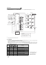
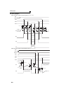
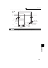
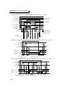
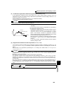
(1) Connection diagram
⋅ The following shows the connection diagram of a typical electronic bypass sequence. Sink logic, Pr. 185 = "7", Pr.
192 = "17", Pr. 193 = "18", Pr. 194 = "19"
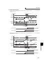
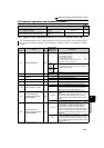
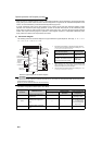
⋅ Operations of magnetic contactors (MC1, MC2, MC3)
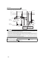
Electronic bypass sequence connection diagram
*1 Take caution for the capacity of the sequence output terminal.
The used terminal changes depending on the setting of Pr. 190 to
Pr. 196 (output terminal function selection).
*2 When connecting a DC power supply, insert a protective diode.
When connecting an AC power supply, connect a relay output
option (FR-A7AR) and use a contact output.
*3 The used terminal changes depending on the setting of Pr. 180 to
Pr. 189 (input terminal function selection).
CAUTION
⋅ Use the bypass operation function in External operation mode. Be sure to connect the other power supply since the function is
not performed normally unless the connection terminals R1/L11, S1/L21 are not connected to the other power supply (power
supply that does not pass MC1).
⋅ Be sure to provide mechanical interlocks for MC2 and MC3
.
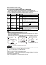
Magnetic
Contactor
Installation Place
Operation ({: Shorted, ×: Open)
Bypass operation
During inverter
operation
At an inverter fault
occurrence
MC1
Between power supply and
inverter input
×
(Shorted by reset)
MC2
Between power supply and
motor
×
×
(Can be selected using
Pr. 138, always open
when external thermal
relay is ON)
MC3
Between inverter output and
motor
×
×
Inverter start
(forward rotation)
MC1
R/L1
S/L2
T/L3
STF
R1/L11
S1/L21
CS
MRS
RES
10
2
5
U
V
W
External
thermal relay
IM
(MC1)IPF
(MC2)OL
SE
MC3
MC2
24VDC
MC
1
External
thermal reset
Frequency
setting signal
(MC3)FU
Inverter/bypass
operation
interlock
MC
2
MC
3
*3
*1
*2
*1
*1
JOG(OH)
MCCB
MC2
MC3
SD
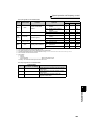
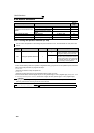
Output Terminal Capacity
Output Terminal
Permissible Load
Inverter open collector output
(RUN, SU, IPF, OL, FU)
24VDC 0.1A
Inverter relay output (A1 and C1,
B1 and C1, A2 and B2, B2 and C2)
Relay output option (FR-A7AR)
230VAC 0.3A
30VDC 0.3A