


145
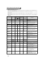
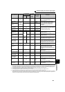
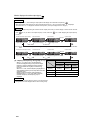
Monitor display and monitor output signal
4
PARAMETERS
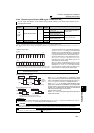
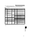
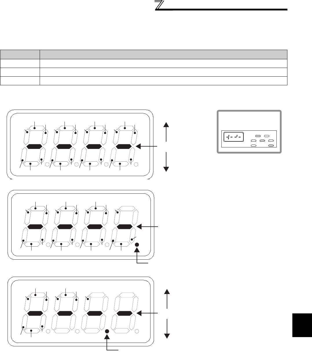
(3) Operation panel (FR-DU07) I/O terminal monitor (Pr. 52)
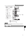
⋅ When Pr. 52 is set to any of "55 to 57", the I/O terminal states can be monitored on the operation panel (FR-DU07).
⋅ The I/O terminal monitor is displayed on the third monitor.
⋅ The LED is ON when the terminal is ON, and the LED is OFF when the terminal is OFF. The center line of LED is
always ON.
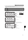
⋅ On the unit I/O terminal monitor (Pr. 52 = "55"), the upper LEDs denote the input terminal states and the lower the
output terminal states.
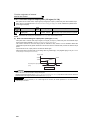
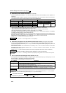
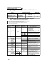
⋅ On the input option terminal monitor (Pr. 52= "56"), the decimal point LED of the first digit LED is ON.
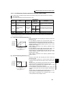
⋅ On the input option terminal monitor (Pr. 52= "57"), the decimal point LED of the second digit LED is ON.
Pr. 52 Setting
Monitor Description
55 Displays the I/O and output terminal ON/OFF states of the inverter unit.
56 * Displays the input terminal ON/OFF states of the digital input option (FR-A7AX).
57 * Displays the output terminal ON/OFF states of the digital output option (FR-A7AY) or relay output option (FR-A7AR).
* You can set "56" or "57" even if the option is not fitted. When the option is not fitted, the monitor displays are all OFF.
RM
RL
RH
RT
MRS
STR
AU RES JOG
SU
IPF
OLRUN
FU
Free
Free
Free
Free
Free
ABC1
ABC2
STOP STF CS
Center line is always ON
Input Terminals
- Display example -
When signals STF,
RH and RUN are ON
Output terminal
MON P.RUN
EXT NETPU
FWD
REV
Hz
A
V
X1
X0
X2
X3
X6
X9
X4 X7
X13
X14
X15X12
Free
Free
DY
Free
Free
Free
X10
X11
X5 X8
Center line is always ON
Decimal point LED of first digit LED is always ON
Y1
Y0
Y2
Y3
Y6
Y4
RA3
RA1
RA2
Y5
Center line is always ON
Decimal point LED of second digit LED is always ON
FR-A7AY
FR-A7AR