


124
Function assignment of external
terminal and control
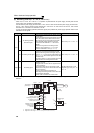
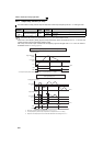
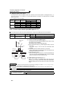
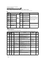
(2) Response time of each signal
⋅ The response time of the X10 signal is within 2ms. However, when the X10 signal is not assigned at the Pr. 30
Regenerative function selection setting of "2" (FR-HC/MT-HC/FR-CV connection), the response time of the MRS
signal is within 2ms.
Pr. 17 MRS input selection is invalid.
4.10.2 Inverter output shutoff signal (MRS signal, Pr. 17)
Pr. 30
Setting
MRS
Assignment
X10
Assignment
Response Time
Pr. 17
MRS X10
2
× Within 2ms ⎯ Invalid
× ⎯ Within 2ms ⎯
Within 20ms Within 2ms Valid
Other than 2
× Within 20ms ⎯ Valid
× ⎯⎯⎯
Within 20ms ⎯ Valid
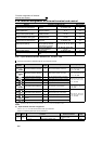
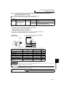
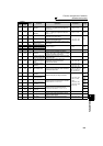
The inverter output can be shut off from the MRS signal. The logic of the MRS signal can also be selected.
Parameter
Number
Name
Initial
Value
Setting
Range
Description
17 MRS input selection 0
0 Open input always
2 Close input always (NC contact input specifications)
The above parameters can be set when Pr. 160 User group read selection = "0". (Refer to page 190)
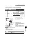
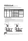
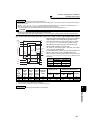
(1) Output shutoff signal (MRS signal)
⋅ Turning ON the output shutoff signal (MRS) during inverter running
shuts off the output immediately.
⋅ Terminal MRS may be used as described below.
(a) When mechanical brake (e.g. electromagnetic brake) is used to
stop motor
The inverter output is shut off when the mechanical brake
operates.
(b) To provide interlock to disable operation by the inverter
With the MRS signal ON, the inverter cannot be operated if the
start signal is entered into the inverter.
(c) Coast the motor to a stop.
When the start signal is turned OFF, the inverter decelerates the
motor to a stop in the preset deceleration time, but when the MRS
signal is turned ON, the motor coasts to a stop.
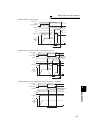
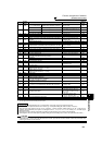
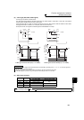
(2) MRS signal logic inversion (Pr. 17)
⋅ When Pr. 17 is set to "2", the MRS signal (output stop) can be
changed to the normally closed (NC contact) input specification.
When the MRS signal turns ON (opens), the inverter shuts off the
output.
REMARKS
⋅ The MRS signal is assigned to the terminal MRS in the initial setting. By setting "24" in either Pr. 178 to Pr. 189 (input terminal
function selection), the RT signal can be assigned to the other terminal.
⋅ When using an external terminal to input the MRS signal, the MRS signal shuts off the output in any of the operation modes.
CAUTION
⋅ Changing the terminal assignment using Pr. 178 to Pr. 189 (input terminal function selection) may affect the other functions. Please
set parameters after confirming the function of each terminal.
♦ Parameters referred to ♦
Pr. 178 to Pr. 189 (Input terminal function selection) Refer to page 122
ON
ON
MRS signal
STF (STR)
signal
Motor coasts
to stop
Time
(Initial
value)
Output
stop
Output
stop
MRS
Inverter
MRS
Inverter
Setting value "0"
Setting value "2"
SD SD