


14
Wiring
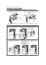
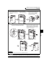
2.1 Wiring
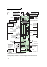
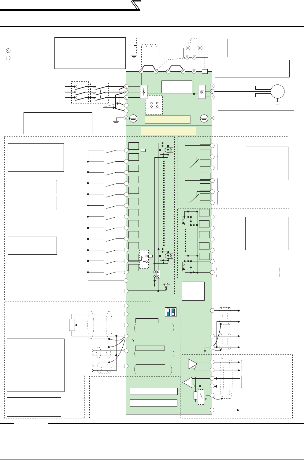
2.1.1 Terminal connection diagram
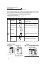
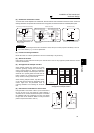
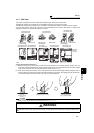
CAUTION
· To prevent a malfunction due to noise, keep the signal cables more than 10cm (3.94inches) away from the power cables. Also
separate the main circuit wire of the input side and the output side.
· After wiring, wire offcuts must not be left in the inverter.
Wire offcuts can cause an alarm, failure or malfunction. Always keep the inverter clean.
When drilling mounting holes in an enclosure etc. take care not to allow chips and other foreign matter to enter the inverter.
· Set the voltage/current input switch correctly. Operation with a wrong setting may cause a fault, failure or malfunction.
Three-phase AC
power supply
MCCB
Jumper
R/L1
S/L2
T/L3
R1/L11
S1/L21
PC
10E(+10V)
10(+5V)
2
3
1
1
4
Control input signals (No voltage input allowed)
Jumper
Motor
Relay output 1
(Fault output)
C1
B1
A1
U
V
W
AM
5
*1
Main circuit terminal
Control circuit terminal
MC
Main circuit
Control circuit
C2
B2
A2
Relay output 2
Relay output
IM
AU
PTC
TXD+
TXD-
RXD+
RXD-
SG
SINK
SOURCE
Terminal functions
vary with the output
terminal assignment
(Pr. 195, Pr. 196)
Terminal functions
vary with the output
terminal assignment
(Pr. 190 to Pr. 194)
Terminal functions vary
with the input terminal
assignment
(Pr. 178 to Pr. 189)
*3
STF
STR
STOP
RH
RM
RL
JOG
RT
MRS
RES
AU
CS
SD
RUN
SU
IPF
OL
FU
SE
EMC filter
ON/OFF
connector
ON
OFF
VCC
Frequency setting signal (Analog)
Frequency setting
potentiometer
1/2W1k
Ω
Auxiliary
input
(+)
(-)
2
(Analog common)
0 to 5VDC
0 to 10VDC
selectable
selectable
selectable
0 to 20mADC
*
4
5
PU
connector
Terminal
4 input
(Current
input)
Terminating
resistor
Connector
for plug-in option
connection
*
5. It is recommended to use
2W1kΩ when the
frequency setting signal is
changed frequently.
(+)
(-)
0 to 5VDC
0 to 10VDC
*
4
GND
RS-485 terminals
Data transmission
Data reception
4 to 20mADC
*
4
0 to ±5VDC
0 to
±
10VDC
(-)
(+)
(0 to 10VDC)
Analog signal output
Frequency detection
Open collector output common
Sink
/source common
Running
Up to frequency
Instantaneous
power failure
Overload
Open collector output
Terminal 4 input selection
(Current input selection)
Selection of automatic restart
after instantaneous
power failure
Output stop
Reset
*3. AU terminal can be
used as PTC input
terminal.
Middle speed
High speed
Low speed
Jog operation
Second function selection
Multi-speed
selection
Forward
rotation
start
Reverse
rotation
start
Start self-holding selection
PR
*7
PX
*7
Jumper
*7.
*5
(Permissible load
current 100mA)
5V
*2. To supply power to the
control circuit separately,
remove the jumper across
R1/L11 and S1/L21.
*2
Do not use PR and PX terminals.
Please do not remove the jumper
connected to terminal PR and PX.
Initial
value
Initial
value
Initial value
*
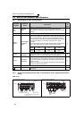
4. Terminal input specifications
can be changed by analog
input specifications switchover
(Pr. 73, Pr. 267). Set the
voltage/current input switch in
the OFF position to select
voltage input (0 to 5V/0 to
10V) and ON to select current
input (0 to 20mA).
ON
4
2
OFF
Voltage/current
input switch
*4
Resistor unit
(Option)
Brake unit
(Option)
CN8
*6
24V
Inrush current
limit circuit
N/-
P/+
P1
Sink logic
Ground
Ground
Ground
(0 to 20mADC)
(-)
(+)
CA
(-)
(+)
CA
Analog current output
(-)
(+)
CA
24VDC power supply
(Common for external power supply transistor)
Contact input common
*6. A CN8 (for MT-BU5) connector is
provided for the FR-F720-03160
(FR-F740-01800) or more.
*1.
DC reactor (FR-HEL)
Be sure to connect the DC reactor
supplied with the FR-F720-03160
(FR-F740-01800) or more
.
When a DC reactor is connected to
the 02330 (FR-F740-01160) or less,
remove the jumper across P1 and P/+.
*8.
The 200V class 00046 and 00077
are not provided with the ON/OFF
connector EMC filter.
*8
Option connector 1
Option connector 2
(Refer to page 128)
(Refer to page 122)
(Refer to page 128)
(Refer to page 171)