


55
Failsafe of the system which uses
the inverter
3
PRECAUTIONS FOR USE OF THE INVERTER
3.6 Failsafe of the system which uses the inverter
When a fault occurs, the inverter trips to output a fault signal. However, a fault output signal may not be output at an inverter
fault occurrence when the detection circuit or output circuit fails, etc. Although Mitsubishi assures best quality products,
provide an interlock which uses inverter status output signals to prevent accidents such as damage to machine when the
inverter fails for some reason and at the same time consider the system configuration where failsafe from outside the inverter,
without using the inverter, is enabled even if the inverter fails.
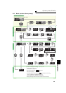
(1) Interlock method which uses the inverter status output signals
By combining the inverter status output signals to provide an interlock as shown below, an inverter alarm can be
detected.
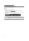
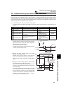
No Interlock Method Check Method Used Signals Refer to Page
1)
Inverter protective
function operation
Operation check of an alarm contact
Circuit error detection by negative logic
Fault output signal
ALM signal
128
2) Inverter running status Operation ready signal check
Operation ready signal
(RY signal)
128
3) Inverter running status
Logic check of the start signal and
running signal
Start signal
(STF signal, STR signal)
Running signal (RUN signal)
126, 128
4) Inverter running status
Logic check of the start signal and
output current
Start signal
(STF signal, STR signal)
Output current detection signal
Y12 signal
126, 135
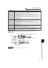
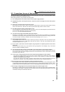
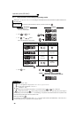
1) Check by the output of the inverter fault signal
When the fault occurs and the inverter trips, the fault output
signal (ALM signal) is output (ALM signal is assigned to
terminal A1B1C1 in the initial setting).
Check that the inverter functions properly.
In addition, negative logic can be set (ON when the inverter
is normal, OFF when the fault occurs).
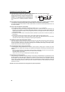
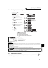
2) Checking the inverter operating status by the inverter
operation ready completion signal
Operation ready signal (RY signal) is output when the
inverter power is ON and the inverter becomes operative.
Check if the RY signal is output after powering ON the
inverter.
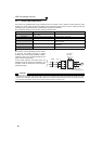
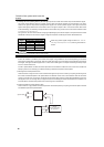
3) Checking the inverter operating status by the start signal
input to the inverter and inverter running signal.
The inverter running signal (RUN signal) is output when the
inverter is running (RUN signal is assigned to terminal RUN
in the initial setting).
Check if RUN signal is output when inputting the start signal
to the inverter (forward signal is STF signal and reverse
signal is STR signal). For logic check, note that RUN signal
is output for the period from the inverter decelerates until
output to the motor is stopped, configure a sequence
considering the inverter deceleration time
ON
Reset processing
(about 1s)
OFF
Reset ON
Output frequency
ALM
(when output
at NC contact)
RES
Inverter fault occurrence
(trip)
Time
OFF
ON
Time
Power
supply
Output frequency
STF
RH
RY
Reset
processing
Pr. 13 Starting frequency
ON OFF
ON OFF
ON OFF
ON
DC injection brake
operation point
DC injection
brake operation
RUN
ON OFF