


341
Causes and corrective actions
5
PROTECTIVE FUNCTIONS
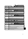
Operation Panel
Indication
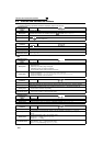
E.UVT
FR-PU04
FR-PU07(-01)
Under Voltage
Name
Undervoltage
Description
If the power supply voltage of the inverter decreases, the control circuit will not perform normal functions.
In addition, the motor torque will be insufficient and/or heat generation will increase. To prevent this, if
the power supply voltage decreases below about 150V (300VAC for the 400V class), this function
stops the inverter output.
When a jumper is not connected across P/+ and P1, the undervoltage protective function is activated.
When undervoltage protection is activated, the IPF signal is output. (Refer to page 152)
Check point
· Check for start of large-capacity motor.
· Check that a jumper or DC reactor is connected across terminals P/+ and P1.
Corrective action
· Check the power supply system equipment such as the power supply.
· Connect a jumper or DC reactor across terminals P/+ and P1.
· If the problem still persists after taking the above measure, please contact your sales representative.
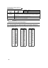
Operation Panel
Indication
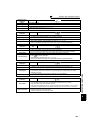
E.ILF
FR-PU04 Fault 14
FR-PU07(-01) Input phase loss
Name
Input phase loss
Description
This fault is output when function valid setting (=1) is set in Pr. 872 Input phase loss protection selection
and one phase of the three phase power input is lost.
When the setting of Pr. 872 Input phase loss protection selection is the initial value (Pr. 872 = "0"), this fault
does not occur. (Refer to page 162.)
Check point
Check for a break in the cable for the three-phase power supply input.
Corrective action
· Wire the cables properly.
· Repair a break portion in the cable.
· Check the Pr. 872 Input phase loss protection selection setting.
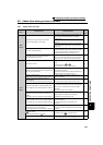
Operation Panel
Indication
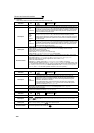
E.OLT
FR-PU04
FR-PU07(-01)
Stll Prev STP ( OL shown during stall
prevention operation)
Name
Stall prevention stop
Description
If the frequency has fallen to 0.5Hz by stall prevention operation and remains for 3s, a fault (E.OLT)
appears and trips the inverter. OL appears while stall prevention is being activated.
Check point
· Check the motor for use under overload. (Refer to page 82.)
Corrective action
· Reduce the load weight.
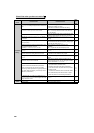
Operation Panel
Indication
E.GF
FR-PU04
FR-PU07(-01)
Ground Fault
Name
Output side earth (ground) fault overcurrent
Description
This function stops the inverter output if an earth (ground) fault overcurrent flows due to an earth
(ground) fault that occurred on the inverter's output (load) side.
Check point Check for an earth (ground) fault in the motor and connection cable.
Corrective action Remedy the earth (ground) fault portion.
Operation Panel
Indication
E.LF
FR-PU04
E. LF
FR-PU07(-01)
Name
Output phase loss
Description
This function stops the inverter output if one of the three phases (U, V, W) on the inverter's output side
(load side) is lost.
Check point
· Check the wiring (Check that the motor is normal.)
· Check that the capacity of the motor used is not smaller than that of the inverter.
⋅ Check if a start command is given to the inverter while the motor is coasting.
Corrective action
· Wire the cables properly.
· Check the Pr. 251 Output phase loss protection selection setting.
· Input a start command after the motor stops. Alternatively, use the automatic restart after
instantaneous power failure/flying start function. (Refer to page 152.)