


213
Communication operation and setting
4
PARAMETERS
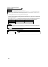
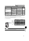
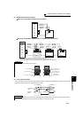
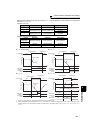
(4) RS-485 terminal wiring method
z Wiring of one RS-485 computer and one inverter
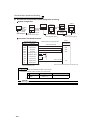
z Wiring of one RS-485 computer and "n" inverters (several inverters)
*1 Make connections in accordance with the manual of the computer used.
Fully check the terminal numbers of the computer since they change with the model.
*2 For the inverter farthest from the computer, set the terminating resistor switch to ON (100
Ω side).
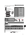
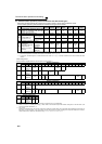
(5) 2-wire type connection
If the computer is 2-wire type, pass wires across receiving terminals and transmission terminals of the RS-485
terminals to enable 2-wire type connection with the inverter.
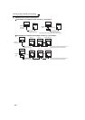
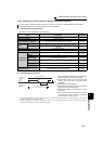
REMARKS
For branching, connect the wires as shown below.
REMARKS
A program should be created so that transmission is disabled (receiving state) when the computer is not sending and reception is
disabled (sending state) during sending to prevent the computer from receiving its own data.
*1
Computer
RDA
RDB
SDA
SDB
RSA
SG
RSB
CSA
CSB
FG
SG
*2
-
+
-
+
SDB1
SDA1
RDB1
RDA1
*1
Computer
RDA
RDB
SDA
SDB
RSA
SG
RSB
CSA
CSB
FG
Station 0
SG SG
-
+
-
+
-
+
-
+
Station 1
SG
SG
-
+
+
-
-
+
+
-
Station n
SG
*2
-
+
SDB1
SDA1
RDB1
RDA1
RDA2
RDB2
SDA2
SDB2
SDB1
SDA1
RDB1
RDA1
SDB1
SDA1
RDB1
RDA1
RDA2
RDB2
SDA2
SDB2
-
+
To computer send
To computer receive
To computer ground
TXD
RXD
VCC
RXD
VCC
TXD
SGSG SGSG
+
-
+
-
+
-
+
-
+
-
+
+
++++
-
--
+
-
+
-
+
+
-
+
-
To receiving terminal
of the next inverter
To receiving terminal
of the next inverter
To next inverter
To earth terminal
To computer send
To computer receive
To computer ground
TXD
RXD
VCC
RXD
VCC
TXD
SGSG SGSG
+
-
+
-
+
-
+
-
+
-
+
+
++++
-
--
+
-
+
-
+
+
-
+
-
To receiving terminal
of the next inverter
To receiving terminal
of the next inverter
To next inverter
To ground terminal
TXD+
TXD-
RXD+
RXD-
SG
SG
InverterComputer
Pass a wire
Transmission
enable
Reception
enable