


21
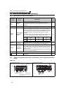
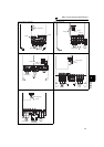
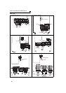
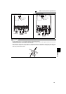
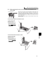
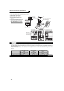
Main circuit terminal specifications
2
WIRING
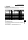
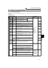
2.2.3 Cables and wiring length
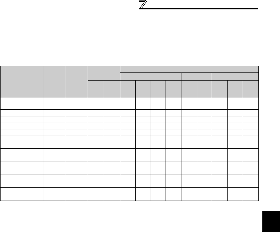
(1) Applicable cable size
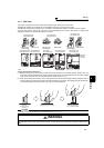
Select the recommended cable size to ensure that a voltage drop will be 2% or less.
If the wiring distance is long between the inverter and motor, a main circuit cable voltage drop will cause the motor
torque to decrease especially at the output of a low frequency.
The following table indicates a selection example for the wiring length of 20m (65.62feet).
200V class (when input power supply is 220V)
Applicable Inverter
Model
Terminal
Screw
Size *4
Tightening
Torque
N·m
Crimping
Terminal
Cable Sizes
HIV, etc. (mm
2
) *1
AWG/MCM *2
PVC, etc. (mm
2
) *3
R/L1,
S/L2,
T/L3
U, V, W
R/L1,
S/L2,
T/L3
U, V, W P/+, P1
Earth
(ground)
cable
R/L1,
S/L2,
T/L3
U, V, W
R/L1,
S/L2,
T/L3
U, V, W
Earth
(ground)
cable
FR-F720-00046 to
00105-NA
M4 1.5 2-4 2-4 2 2 2 2 14 14 2.5 2.5 2.5
FR-F720-00167-NA M4 1.5 5.5-4 5.5-4 3.5 3.5 3.5 3.5 12 12 4 4 4
FR-F720-00250-NA M4 1.5 5.5-4 5.5-4 5.5 5.5 5.5 5.5 10 10 6 6 6
FR-F720-00340-NA M5 2.5 14-5 8-5 14 8 14 5.5 6 8 16 10 16
FR-F720-00490-NA M5 2.5 14-5 14-5 14 14 14 14 6 6 16 16 16
FR-F720-00630-NA M5 2.5 22-5 22-5 22 22 22 14 4 6 (
*5)25 25 16
FR-F720-00770-NA M6 4.4 38-6 38-6 38 38 38 22 2 2 50 50 25
FR-F720-00930-NA M8(M6) 7.8 38-8 38-8 38 38 38 22 2 2 50 50 25
FR-F720-01250-NA M8(M6) 7.8 60-8 60-8 60 60 60 22 1/0 1/0 50 50 25
FR-F720-01540-NA M8(M6) 7.8 80-8 80-8 80 80 80 22 3/0 3/0 70 70 35
FR-F720-01870-NA M10(M8) 14.7 100-10 100-10 100 100 100 38 4/0 4/0 95 95 50
FR-F720-02330-NA M10(M8) 14.7 100-10 100-10 100 100 100 38 4/0 4/0 95 95 50
FR-F720-03160-NA M12(M10) 24.5 150-12 150-12 125 125 150 38 250 250 ⎯⎯⎯
FR-F720-03800-NA M12(M10) 24.5 150-12 150-12 150 150 2×100 38 2×4/0 2×4/0 ⎯⎯⎯
FR-F720-04750-NA M12(M10) 24.5 100-12 100-12 2×100 2×100 2×100 38 2×4/0 2×4/0 ⎯⎯⎯
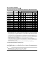
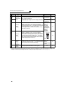
*1 The recommended cable size is that of the cable (e.g. HIV cable (600V class 2 vinyl-insulated cable)) with co
ntinuous maximum permissible
temperature of 75°C (167°F). Assumes that the surrounding air temperature is 50°C (122°F) or less and the wiring distance is 20m (65.62feet) or
les
s.
*2 The recommended cable size is that of the cable (THHW cable) with continuous maximum permissible temperature of 75°C (167°F). Assumes
that the surrounding air temperature is 40°C (104°F) or l
es
s and the wiring distance is 20m (65.62feet) or less.
(Selection example for use mainly in the United States.)
*3 For the FR-F720-00930 or less, the recommended cable size is that of the cable (PVC cable) with continuous maximum permissible temperature
of 70°C (158°F). Assumes that the surrounding air temperature is 40°C (104°F) or
l
ess and the wiring distance is 20m(65.62feet) or less.
For the FR-F720-01250 or more, the recommended cable size is that of the cable (XLPE cable) with continuous maximum permissible
temperature of 90°C (194°F). As
sum
es that the surrounding air temperature is 40°C (104°F) or less and wiring is performed in an enclosure.
(Selection example for use mainly in Europe.)
*4 The terminal screw size indicates the terminal size for R/L1, S/L2, T/L3, U, V, W, PR, PX, P/+, N/-, P1 and a screw for grounding.
A screw for earthing (grounding) of the FR-F720-00930 or more is indicated in ( ).
*5 When connecting the option unit to P/+, P1, N/-, use THHN cables for the option and terminals R/L1, S/L2, T/L3, U, V, W.