


161
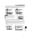
Operation setting at fault occurrence
4
PARAMETERS
4.13.2 Fault code output selection (Pr. 76)
⋅ By setting Pr. 76 to "1" or "2", the fault code can be output to the output terminals.
⋅ When the setting is "2", a fault code is output at only fault occurrence, and during normal operation, the terminals
output the signals assigned to Pr. 191 to Pr. 194 (output terminal function selection).
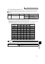
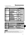
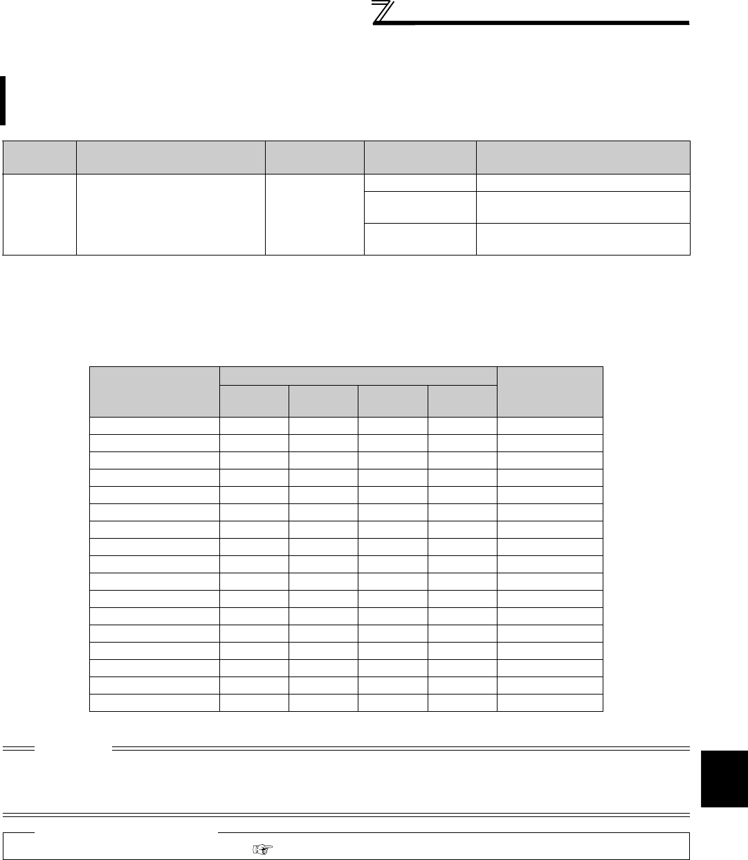
⋅ The following table indicates fault codes to be output. (0: output transistor OFF, 1: output transistor ON)
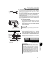
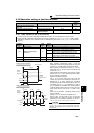
At fault occurrence, its description can be output as a 4-bit digital signal from the open collector output terminals.
The fault code can be read by a programmable controller, etc., and its corrective action can be shown on a
display, etc.
Parameter
Number
Name Initial Value Setting Range Description
76 Fault code output selection 0
0 Without fault code output
1
With fault code output
(Refer to the following table)
2
Fault code output at fault occurrence
only (Refer to the following table)
The above parameters can be set when Pr. 160 User group read selection = "0". (Refer to page 190)
Operation Panel
Indication
(FR-DU07)
Output of Output Terminals
Fault Code
SU IPF OL FU
Normal * 0000 0
E.OC1 0001 1
E.OC2 0010 2
E.OC3 0011 3
E.OV1 to E.OV3 0100 4
E.THM 0101 5
E.THT 0110 6
E.IPF 0111 7
E.UVT 1000 8
E.FIN 1001 9
E. BE 1010 A
E. GF 1011 B
E.OHT 1100 C
E.OLT 1101 D
E.OPT 1110 E
E.OP1 1110 E
Other than the above 1111 F
* When Pr. 76 = "2", the output terminals output the signals assigned to Pr. 191 to Pr. 194 .
CAUTION
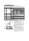
⋅ When a value other than "0" is set in Pr.76
When a fault occurs, the output terminals SU, IPF, OL, FU output the signal in the above table, independently of the Pr. 191 to
Pr. 194 (output terminal function selection) settings. Please be careful when inverter control setting has been made with the output
signals of Pr. 191 to Pr. 194.
♦ Parameters referred to ♦
Pr. 191 to Pr. 194 (output terminal function selection) Refer to page 128