


209
Communication operation and setting
4
PARAMETERS
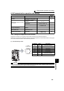
4.19 Communication operation and setting
4.19.1 Wiring and configuration of PU connector
Using the PU connector, you can perform communication operation from a personal computer etc.
When the PU connector is connected with a personal, FA or other computer by a communication cable, a user program
can run and monitor the inverter or read and write to parameters.
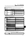
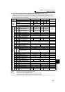
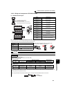
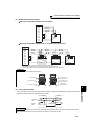
(1) PU connector pin-outs
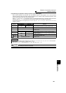
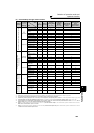
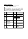
Purpose Parameter that must be Set
Refer to
Page
Communication operation from PU
connector
Initial setting of computer link
communication (PU connector)
Pr. 117 to Pr. 124
214
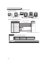
Communication operation from RS-
485 terminals
Initial setting of computer link
communication (RS-485
terminals)
Pr. 331 to Pr. 337, Pr. 341, Pr. 502,
Pr. 779
Modbus-RTU communication
specifications
Pr. 331, Pr. 332, Pr. 334, Pr. 343,
Pr. 502, Pr. 549, Pr. 779
232
BACnet MS/TP protocol
Pr. 331, Pr. 332, Pr. 390, Pr. 549,
Pr. 726 to Pr. 729
247
Restrictions on parameter write
through communication
Communication EEPROM write
selection
Pr. 342 216
Operation selection the at a
communication error
Stop mode selection at
communication error
Pr. 502, Pr. 779 216
Operation by PLC function PLC function
Pr. 414, Pr. 415, Pr. 498,
Pr. 506 to Pr. 515,
Pr. 826 to Pr. 865
260
Pin Number Name Description
1) SG
Ground
(connected to terminal 5)
2) ⎯ Operation panel power supply
3) RDA Inverter receive+
4) SDB Inverter send-
5) SDA Inverter send+
6) RDB Inverter receive-
7) SG
Ground
(connected to terminal 5)
8) ⎯ Operation panel power supply
CAUTION
⋅ Pins No. 2 and 8 provide power to the operation panel or parameter unit. Do not use these pins for RS-485 communication.
⋅ Do not connect the PU connector to the computer's LAN board, FAX modem socket or telephone modular connector. The
product could be damaged due to differences in electrical specifications.
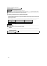
8)
to
1)
Inverter
(Receptacle side
)
Front view