


335
Causes and corrective actions
5
PROTECTIVE FUNCTIONS
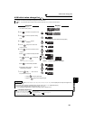
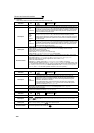
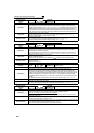
Operation Panel
Indication
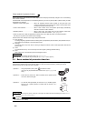
rE1
Name
Parameter read error
Description
An error occurred in the EEPROM on the operation panel side during parameter copy reading.
Check point
--------------
Corrective action
⋅ Make parameter copy again. (Refer to page 325.)
⋅ Check for an operation panel (FR-DU07) failure. Please contact your sales representative.
Operation Panel
Indication
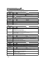
rE2
Name
Parameter write error
Description
⋅ You attempted to perform parameter copy write during operation.
⋅ An error occurred in the EEPROM on the operation panel side during parameter copy writing.
Check point Is the FWD or REV LED of the operation panel (FR-DU07) lit or flickering?
Corrective action
⋅ After stopping operation, make parameter copy again. (Refer to page 325.)
⋅ Check for an operation panel (FR-DU07) failure. Please contact your sales representative.
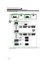
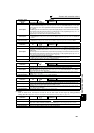
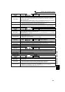
Operation Panel
Indication
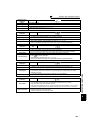
rE3
Name
Parameter verification error
Description
⋅ Data on the operation panel side and inverter side are different.
⋅ An error occurred in the EEPROM on the operation panel side during parameter verification.
Check point Check for the parameter setting of the source inverter and inverter to be verified.
Corrective action
⋅ Press to continue verification.
Make parameter verification again. (Refer to page 326.)
⋅ Check for an operation panel (FR-DU07) failure. Please contact your sales representative.
Operation Panel
Indication
rE4
Name
Model error
Description
⋅ A different model was used for parameter write and verification during parameter copy.
⋅ When parameter copy write is stopped after parameter copy read is stopped
Check point
⋅ Check that the verified inverter is the same model.
⋅ Check that the power is not turned OFF or an operation panel is not disconnected, etc. during
parameter copy read.
Corrective action
⋅ Use the same model (FR-F700 series) for parameter copy and verification.
⋅ Perform parameter copy read again.
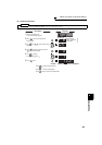
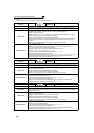
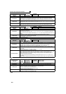
Operation Panel
Indication
Err.
Description
⋅ The RES signal is ON
⋅ PU and inverter cannot make normal communication (contact fault of the connector)
⋅ When the voltage drops in the inverter's input side.
⋅ When the control circuit power (R1/L11, S1/L21) and the main circuit power(R/L1, S/L2, T/L3) are
connected to a separate power, it may appear at turning ON of the main circuit. It is not a fault.
Corrective action
⋅ Turn OFF the RES signal.
⋅ Check the connection of PU and inverter.
⋅ Check the voltage on the inverter's input side.