


339
Causes and corrective actions
5
PROTECTIVE FUNCTIONS
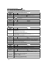
Operation Panel
Indication
E.OV1
FR-PU04
FR-PU07(-01)
OV During Acc
Name
Regenerative overvoltage trip during acceleration
Description
If regenerative energy causes the inverter's internal main circuit DC voltage to reach or exceed the
specified value, the protective circuit is activated to stop the inverter output. The circuit may also be
activated by a surge voltage produced in the power supply system.
Check point
· Check for too slow acceleration. (e.g. during descending acceleration with lifting load)
· Check if Pr. 22 Stall prevention operation level is set too low like the no-load current.
Corrective action
· Decrease the acceleration time.
· Use regeneration avoidance function (Pr. 882 to Pr. 886).
(Refer to page 298.)
· Set a value larger than the no load current in Pr. 22 Stall prevention operation level.
Operation Panel
Indication
E.OV2
FR-PU04
FR-PU07(-01)
Stedy Spd OV
Name
Regenerative overvoltage trip during constant speed
Description
If regenerative energy causes the inverter's internal main circuit DC voltage to reach or exceed the
specified value, the protective circuit is activated to stop the inverter output. The circuit may also be
activated by a surge voltage produced in the power supply system.
Check point
· Check for sudden load change.
· Check if Pr. 22 Stall prevention operation level is set too low like the no-load current.
Corrective action
· Keep load stable.
· Use regeneration avoidance function (Pr. 882 to Pr. 886).
(Refer to page 298.)
· Use the brake unit or power regeneration common converter (FR-CV) as required.
· Set a value larger than the no load current in Pr. 22 Stall prevention operation level.
Operation Panel
Indication
E.OV3
FR-PU04
FR-PU07(-01)
OV During Dec
Name
Regenerative overvoltage trip during deceleration or stop
Description
If regenerative energy causes the inverter's internal main circuit DC voltage to reach or exceed the
specified value, the protective circuit is activated to stop the inverter output. The circuit may also be
activated by a surge voltage produced in the power supply system.
Check point Check for sudden speed reduction.
Corrective action
· Increase the deceleration time. (Set the deceleration time which matches the moment of inertia of the load)
· Longer the brake cycle.
· Use regeneration avoidance function
(Pr. 882 to Pr. 886)
.
(
Refer to page 298
.)
· Use the brake unit or power regeneration common converter (FR-CV) as required.
Operation Panel
Indication
E.THT
FR-PU04
FR-PU07(-01)
Inv. Overload
Name
Inverter overload trip (electronic thermal relay function) *1
Description
If a current not less than 110%*2 of the rated output current flows and overcurrent trip does not occur
(170% or less), the electronic thermal relay activates to stop the inverter output in order to protect the
output transistors. (Overload capacity 110%*2 60s inverse-time characteristic)
Check point
· Check that acceleration/deceleration time is not too short.
· Check that Pr. 0 Torque boost setting is not too large (small). (V/F control)
· Check that Pr. 14 Load pattern selection setting is appropriate for the load pattern of the using
machine. (V/F control)
· Check the motor for use under overload.
Corrective action
· Increase acceleration/deceleration time.
· Adjust the Pr. 0 Torque boost setting.
· Set the Pr. 14 Load pattern selection setting according to the load pattern of the using machine. (V/F
control)
· Reduce the load weight.
*1 Resetting the inverter initializes the internal thermal integrated data of the electronic thermal relay function.
*2 120% when LD is selected