


130
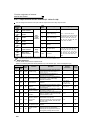
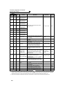
Function assignment of external
terminal and control
71
⎯
RO1
Commercial-power
supply side motor 1
connection RO1
Used when using advanced PID control
(pump function).
Pr. 575 to Pr. 591 283
72
⎯
RO2
Commercial-power
supply side motor 2
connection RO2
73
⎯
RO3
Commercial-power
supply side motor 3
connection RO3
74
⎯
RO4
Commercial-power
supply side motor 4
connection RO4
75
⎯
RIO1
Inverter side motor 1
connection RIO1
76
⎯
RIO2
Inverter side motor 2
connection RIO2
77
⎯
RIO3
Inverter side motor 3
connection RIO3
78
⎯
RIO4
Inverter side motor 4
connection RIO4
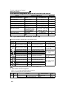
79 179 Y79
Pulse train output of
output power
Output in pulses every time the accumulated
output power of the inverter reaches the
Pr.799 setting.
Pr. 799
138
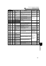
82 182 Y82 BACnet binary output
Control of binary output from BACnet is
available.
⎯ 247
85 185 Y85 DC feeding
Output during power failure or under voltage
of AC power.
Pr. 30, Pr. 70 114
90 190 Y90 Life alarm
Output when any of the control circuit
capacitor, main circuit capacitor and inrush
current limit circuit or the cooling fan
approaches the end of its service life.
Pr. 255 to Pr. 259 301
91 191 Y91
Fault output 3
(power-OFF signal)
Output when a fault occurs due to the
internal circuit failure of inverter wiring
mistake.
⎯ 132
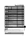
92 192 Y92
Energy saving
average value
updated timing
Turned ON and OFF alternately every time
the power saving average value is updated
when the power saving monitor is used.
Cannot be set to Pr. 195 and Pr. 196 (relay
output terminal).
Pr. 52, Pr. 54,
Pr. 158, Pr. 891 to
Pr. 899
164
93 193 Y93
Current average
value monitor signal
Average current value and maintenance
timer value are output as pulses.
Cannot be set to Pr. 195 and Pr. 196 (relay
output terminal).
Pr. 555 to Pr. 557 305
94 194 ALM2 Fault output 2
Output when the fault occurs. Continues
outputting the signal during inverter reset
and stops outputting after reset is cancelled.
*2
⎯ 132
95 195 Y95
Maintenance timer
signal
Output when Pr. 503 rises to or above the Pr.
504 setting.
Pr. 503, Pr. 504 304
96 196 REM Remote output
Output to the terminal when a value is set to
the parameter.
Pr. 495 to Pr. 497
137
98 198 LF Alarm output
Output when an alarm (fan failure or
communication error warning) occurs.
Pr. 121, Pr. 244
214,
300
99 199 ALM Fault output
Output when the fault occurs. The signal
output is stopped when the fault is reset.
⎯ 132
9999 ⎯ No function ⎯⎯⎯
*1 Note that when the frequency setting is varied using an analog signal or of the operation panel (FR-DU07), the output of the SU (up to
frequency) signal may alternate ON and OFF depending on that varying speed and the timing of the varying speed due to acceleration/
deceleration time setting. (The output will not alternate ON and OFF when the acceleration/deceleration time setting is "0s".)
*2 When a power supply reset is performed, the fault output 2 signal (ALM2) turns OFF as soon as the power supply switches OFF.
Setting
Signal
Name
Function Operation
Related
Parameters
Refer
to Page
Positive
Logic
Negative
Logic