


332
Reset method of protective function
When a fault occurs in the inverter, the inverter trips and the PU display automatically changes to one of the following
fault or alarm indications.
If the fault does not correspond to any of the following faults or if you have any other problem, please contact your sales
representative or distributor.
• Retention of fault output signal ................ When the magnetic contactor (MC) provided on the input side of the
inverter is opened when a fault occurs, the inverter's control power will be
lost and the fault output will not be held.
• Fault or alarm indication .......................... When a fault or alarm occurs, the operation panel display automatically
switches to the fault or alarm indication
• Resetting method..................................... When a fault occurs, the inverter output is kept stopped. Unless reset,
therefore, the inverter cannot restart. (Refer to page 332.)
• When any fault occurs, take the appropriate corrective action, then reset the inverter, and resume operation.
Not doing so may lead to the inverter fault and damage.
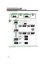
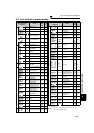
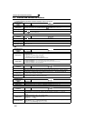
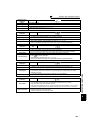
Inverter fault or alarm indications are roughly categorized as below.
(1) Error message
A message regarding operational fault and setting fault by the operation panel (FR-DU07) and parameter unit (FR-
PU04 /FR-PU07) is displayed. The inverter does not trip.
(2) Warnings
The inverter does not trip even when a warning is displayed. However, failure to take appropriate measures will
lead to a fault.
(3) Alarm
The inverter does not trip. You can also output an alarm signal by making parameter setting.
(4) Fault
When a fault occurs, the inverter trips and a fault signal is output.
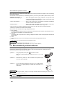
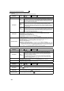
5.1 Reset method of protective function
The inverter can be reset by performing any of the following operations. Note that the internal thermal integrated value
of the electronic thermal relay function and the number of retries are cleared (erased) by resetting the inverter.
Inverter recovers about 1s after the reset is released.
REMARKS
• For the details of fault displays and other troubles, also refer to page 333.
• Past eight faults can be displayed using the setting dial. (Refer to page 59 for the operation.)
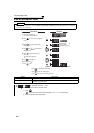
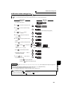
Operation 1: .....Using the operation panel, press to reset the inverter.
(This may only be performed when a fault occurs. (Refer to page 338 for
fault.))
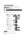
Operation 2:...... Switch OFF the power once. After the indicator of the operation panel
turns OFF, switch it ON again.
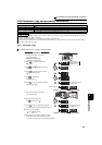
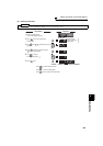
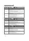
Operation 3: . ....Turn ON the reset signal (RES) for more than 0.1s. (If the RES signal is
kept ON, "Err." appears (flickers) to indicate that the inverter is in a
reset status.)
ON
OFF
Inverter
RES
SD
REMARKS
• When a fault occurs during PLC function, turning ON of X51 signal can release fault without interrupting PLC function. (Refer to
the FR-F700 PLC function programming manual. )
CAUTION
⋅
OFF status of the start signal must be confirmed before resetting the inverter fault. Resetting inverter fault with the start signal
ON restarts the motor suddenly.