


383
Outline dimension drawings
7
SPECIFICATIONS
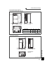
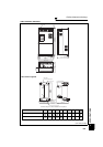
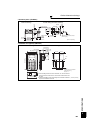
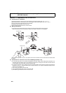
• Operation panel (FR-DU07)
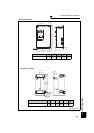
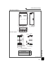
• Parameter unit (option) (FR-PU07)
2-M3 screw
Panel
Cable
Air-
bleeding
hole
FR-DU07
Operation panel connection connector
(FR-ADP option)
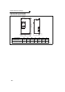
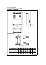
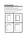
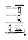
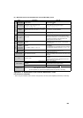
<Outline drawing> <Panel cutting dimension drawing>
78 (3.07)
50 (1.97)
44 (1.73)
72 (2.83)3 (0.12) 3 (0.12)
81 (3.19)
3 (0.12)
3
(0.12)
16 (0.63)
25 (0.98)
3.2 (0.13) max
72 (2.83)
44 (1.73)
21 (0.83)
6 (0.24)
20
(0.79)
27.8
(1.09)
(Unit: mm (inches))
22
(0.87)
80.3 (3.16)
(14.2 (0.56))
2.5
(0.10)
50
(1.97)
(11.45 (0.45))
25.05 (0.97)
135 (5.31)
83 (3.27)
*1
*1
*1
*1
67 (2.64)
51 (2.01)
40 (1.57)
56.8 (2.24)
57.8 (2.28)
26.5
(1.04)
4-R1
4-φ4 hole
(Effective depth of the installation
screws hole 5.0 (0.2))
M3 screw *2
26.5
(1.04)
40 (1.57)
Air-bleeding
hole
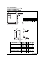
<Outline drawing> <Panel cutting dimension drawing>
(Unit: mm (inches))
*1 When installing the FR-PU07 on the enclosure, etc., remove screws for
fixing the FR-PU07 to the inverter or fix the screws to the FR-PU07 with
M3 nuts.
*2 Select the installation screws whose length will not exceed the effective
depth of the installation screw hole.