


149
Monitor display and monitor output signal
4
PARAMETERS
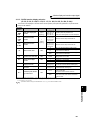
4.11.4 Terminal CA, AM calibration
(Calibration parameter C0 (Pr. 900), C1 (Pr. 901), C8 (Pr.930) to C11 (Pr. 931))
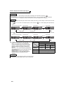
(1) CA terminal calibration (C0(Pr. 900), C8(Pr. 930) to C11(Pr. 931) )
⋅ Calibrate CA terminal in the following procedure.
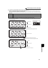
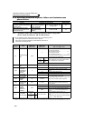
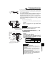
1) Connect a 0-20mADC meter (DC ammeter) to across inverter terminals CA and 5. (Note the polarity. Terminal
CA is plus.)
2) Set calibration parameters C8(Pr. 930) to C11 (Pr. 931) to initial values. (When the meter needle does not point to
0, calibrate using C8(Pr. 930) and C9(Pr. 930))
3) Refer to the monitor description list (page 142) to set Pr. 54.
When running frequency, inverter output current or the like has been selected as the monitor, preset in Pr. 55 or
Pr. 56 the running frequency or current value at which the output signal is 20mA.
4) Run the inverter. (The inverter may be run in either the PU or External operation mode.)
5) Use calibration parameter C0(Pr. 900) to set the meter needle to point to full-scale.
By using the operation panel or parameter unit, you can calibrate terminal CA and terminal AM to full scale
deflection.
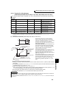
Parameter
Number
Name Initial Value Setting Range Description
C0(900) CA terminal calibration ⎯⎯
Calibrates the scale of the meter
connected to terminal CA.
C1(901) AM terminal calibration ⎯⎯
Calibrates the scale of the analog
meter connected to terminal AM.
C8(930) Current output bias signal 0% 0 to 100%
Output signal value for minimum
analog current output
C9(930) Current output bias current 0% 0 to 100%
Output current value for minimum
analog current output
C10(931) Current output gain signal 100% 0 to 100%
Output signal value for maximum
analog current output
C11(931) Current output gain current 100% 0 to 100%
Output current value for maximum
analog current output
*1 The above parameters can be set when Pr. 160 User group read selection = "0". (Refer to page 190.)
*2 The parameter number in parentheses is the one for use with the parameter unit (FR-PU04/FR-PU07).
*3 The above parameters allow its setting to be changed during operation in any operation mode even if "0" (initial value) is set in Pr. 77 Parameter
write selection.
⋅ Terminal CA is factory-set to provide a 20mADC
output in the full-scale status of the corresponding
monitor item. Calibration parameter C0 (Pr. 900) allows
the output current ratios (gains) to be adjusted
according to the meter scale. Note that the maximum
output current is 20mADC.
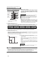
⋅ Use calibration parameters C8(Pr. 930) and C9(Pr. 930)
to set a value for zero analog current output (meter
points zero) . In addition, use calibration parameters
C10(Pr. 931) and C11(Pr. 931) to set a value for
maximum analog current output.
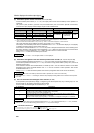
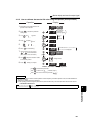
⋅ Use calibration parameters C8(Pr. 930) and C10(Pr.931)
to set output signal values (monitor output set in Pr. 54)
when the current output at terminal CA is zero or
maximum. At this time, the full-scale of each monitor is
100%. (Refer to page 142)
⋅ Use calibration parameters C9(Pr. 930) and C11(Pr.931)
to set the current output values at terminal CA when
the output signal value (monitor output set in Pr. 54) is
zero or maximum. At this time, the current output
calibrated using calibration parameter C0(Pr. 900) is
100%.
REMARKS
⋅ When calibrating a monitor output signal, which cannot be adjusted to 100% value without an actual load and a measurement
equipment, set Pr. 54 to "21" (reference voltage output). (20mADC is output at terminal CA.)
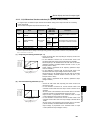
⋅ Even when calibration parameters are set as C8(Pr. 930) ≥ C10(Pr. 931) and C9(Pr. 930) ≥ C11(Pr. 931), current can be output at
terminal CA.
(ammeter)
0 to 20mADC
CA
5
(+) (-)
Analog output current
(CA)
20mA
C0(Pr.900)
100%
0
Output signal value
Output signal value
for minimum analog output
(C10(Pr.931))
Output signal value
for zero analog current output
(C8(Pr.930))
Analog current output value for zero output signal
(C9(Pr.930))
Analog current output
value for maximum
output signal
(C11(Pr.931))