


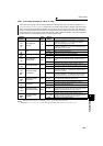
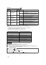

282
PID control
765
Second pre-charge
fault selection
0
0
When the pre-charged amount exceeds Pr. 768 or the pre-
charged time exceeds Pr. 769 while the RT signal is ON, the
fault (E.PCH) is output.
1
When the pre-charged amount exceeds Pr. 768 or the pre-
charged time exceeds Pr. 769 while the RT signal is ON, the
motor decelerates to stop, and the fault (E.PCH) is output.
766
Second pre-charge
ending level
9999
0 to 100%
*3
Set the measurement level to end the pre-charge operation,
which is performed while the RT signal is ON.
9999 Without second pre-charge ending level
767
Second pre-charge
ending time
9999
0.0 to 3600s
Set the time to end the pre-charge operation, which is
performed while the RT signal is ON.
9999 Without second pre-charge ending time
768
Second pre-charge
upper detection level
9999
0 to 100%
*3
Set the upper limit for the pre-charged amount, which is
charged while the RT signal is ON. If the pre-charged amount
exceeds the set level, the fault (E.PCH) is output.
9999 Without second pre-charge ending level
769
Second pre-charge
time limit
9999
0.0 to 3600s
Set the time limit for the pre-charge operation, which is
performed while the RT signal is ON. If the pre-charged time
exceeds the set level, the fault (E.PCH) is output.
9999 Without second pre-charge time limit
The above parameters can be set when Pr. 160 User group read selection = "0". (Refer to page 190)
... Specifications differ according to the date assembled. Refer to page 400 to check the SERIAL number.
*1 The above parameters allow its setting to be changed during operation in any operation mode even if "0" (initial value) is set in Pr. 77 Parameter
write selection.
*2 PID control is available without turning X14 signal ON when Pr.128 = "50, 51, 60, 61, 110, 111, 120, 120".
*3 Setting values of Pr.755, Pr.766, Pr.768 are without unit when "9999" is set to both of C42(Pr.934) and C44(Pr.935).
*4 Input specification for the terminals are determined by Pr.73 Analog input selection.
*5 Input specification for the terminal is determined by Pr.267 Terminal 4 input selection.
*6 Refer to the FR-F700 PLC function programming manual for details of the PLC function.
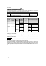
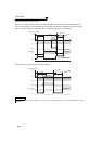
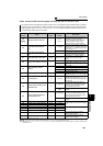
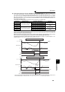
Normal PID control (RT signal is OFF) Second PID control (RT signal is ON)
Pr.128 PID action selection Pr.753 Second PID action selection
Pr.127 PID control automatic switchover frequency
Pr.754 Second PID control automatic switchover
frequency
Pr.133 PID action set point Pr.755 Second PID action set point
Pr.129 PID proportional band Pr.756 Second PID proportional band
Pr.130 PID integral time Pr.757 Second PID integral time
Pr.134 PID differential time Pr.758 Second PID differential time
Pr.760 Pre-charge fault selection Pr.765 Second pre-charge fault selection
Pr.761 Pre-charge ending level Pr.766 Second pre-charge ending level
Pr.762 Pre-charge ending time Pr.767 Second pre-charge ending time
Pr.763 Pre-charge upper detection level Pr.768 Second pre-charge upper detection level
Pr.764 Pre-charge time limit Pr.769 Second pre-charge time limit
REMARKS
⋅ The control switches between PID control and second PID control by the following operation:
⋅ Turning ON/OFF the RT signal while Pr. 753 ≠ 9999
⋅ Setting "9999" or a value other than "9999" in Pr. 753 while the RT signal is ON.
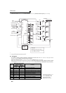
⋅ The RT signal acts as the second function selection signal and makes the other second functions valid. (Refer to page 125)
⋅ In the initial setting, the RT signal is assigned to the RT terminal. By setting "3" to any of Pr. 178 to Pr. 189 (Input terminal function
selection), you can assign the RT signal to the other terminal.
♦ Parameters referred to ♦
Pr. 59 Remote function selection Refer to page 98
Pr. 73 Analog input selection Refer to page 171
Pr. 79 Operation mode selection Refer to page 195
Pr. 178 to Pr. 189 (input terminal function selection) Refer to page 122
Pr. 190 to Pr. 196 (output terminal function selection) Refer to page 128
Pr. 759 PID unit selection Refer to page 261
C2 (Pr. 902) to C7 (Pr. 905) Frequency setting voltage (current) bias/gain Refer to page 177
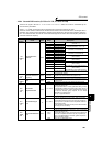
Parameter
Number
Name
Initial
Value
Setting
Range
Description