


2
Product checking and parts identification
1.1 Product checking and parts identification
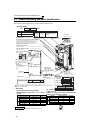
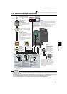
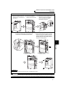
Unpack the inverter and check the capacity plate on the front cover and the rating plate on the inverter side face to
ensure that the product agrees with your order and the inverter is intact.
Operation panel (FR-DU07)
Front cover
EMC filter ON/OFF connector
Control circuit
terminal block
AU/PTC switchover switch
Main circuit terminal block
Charge lamp
Lit when power is
supplied to the main
circuit
Power lamp
Lit when the control circuit
(R1/L11, S1/L21) is supplied
with power.
Cooling fan
PU connector
RS-485 terminals
Alarm lamp
Lit when the inverter is
in the alarm status
(fault).
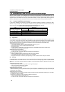
Capacity plate
Inverter model
Serial number
Capacity plate
Rating plate
Voltage/current input switch
Connector for plug-in option connection
(Refer to the Instruction Manual of options.)
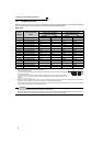
00126
FR-F740-00126-NA
- NA
FR --F740
Symbol
F720
Voltage Class
Three-phase 200V class
F740 Three-phase 400V class
Symbol
200V class
00046
to
04750
Represents the rated
current
Model Number
400V class
00023
to
12120
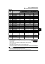
Rating plate
Inverter model
Input rating
Output rating
Serial number
FR-F740-00126-NA
LD (50 C) XXA
SLD (40 C) XXA
• Inverter Model
wiring cover
Surrounding Air
Temperature
LD 120% 60s, 150% 3s 50 C (122 F)
SLD 110% 60s, 120% 3s 40 C (104 F)
Overload Current Rating
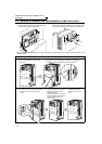
There are two connection connectors, and they are
called connector 1 and connector 2 from the top.
(Refer to page 34)
(Refer to page 6)
(Refer to page 15)
(Refer to page 16)
(Refer to page 360)
(Refer to page 35)
(Refer to page 110)
(Refer to page 27)
(Refer to page 20)
(Refer to page 6)
(Refer to page 16)
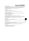
• Accessory
· Fan cover fixing screws (FR-F720-01250
(FR-F740-00620) or less) (Refer to the Installation
Guideline)
Capacity Screw Size (mm) Number
200V
00105 to 00250 M3 × 35 1
00340 to 00630 M4 × 40 2
00770 to 01250 M4 × 50 1
400V
00083, 00126 M3 × 35 1
00170 to 00380 M4 × 40 2
00470, 00620 M4 × 50 1
· DC reactor supplied (FR-F720-03160 (FR-F740-
01800) or more)
· Eyebolt for hanging the inverter (FR-F720-01540
to 04750, FR-F740-00770 to 06830)
Model Eyebolt Size (mm) Number
200V
01540 M8 2
01870 to 04750 M10 2
400V
00770 M8 2
00930 to 03610 M10 2
04320 to 06830 M12 2
(Refer to page 14, 171)
REMARKS
For removal and reinstallation of covers, refer to page 6.
... Specifications differ according to the date assembled. Refer to page 400 to check
the SERIAL number.