


38
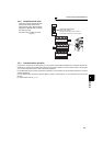
Connection of stand-alone option units
2.4.2 Connection of the brake unit (FR-BU/MT-BU5)
When connecting the brake unit (FR-BU(H)/MT-BU5) to improve the brake capability at deceleration, make connection
as shown below.
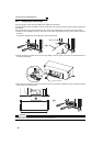
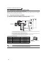
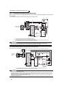
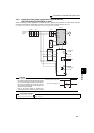
(1) Connection with the FR-BU (FR-F720-02330 (FR-F740-01160) or less)
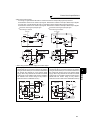
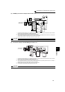
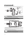
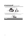
(2) Connection with the MT-BU5 (FR-F720-03160 (FR-F740-01800) or more)
After making sure that the wiring is correct, set "1" in Pr.30 Regenerative function selection. (Refer to page 114)
*1 Connect the inverter terminals (P/+, N/-) and brake unit (FR-BU (H)) terminals so that their terminal signals match
with each other. (Incorrect connection will damage the inverter.)
*2 When the power supply is 400V class, install a step-down transformer.
*3 The wiring distance between the inverter, brake unit (FR-BU) and resistor unit (FR-BR) should be within 5m(16.4
feet). If twisted wires are used, the distance should be within 10m(32.8feet).
CAUTION
⋅ If the transistors in the brake unit should become faulty, the resistor can be unusually hot, causing a fire. Therefore, install a
magnetic contactor on the inverter’s input side to configure a circuit so that a current is shut off in case of fault.
⋅ Do not remove a jumper across terminal P/+ and P1 except when connecting a DC reactor.
*1 When the power supply is 400V class, install a step-down transformer.
*2 The wiring length between the resistor unit and brake resistor should be 10m(32.8feet) maximum when
wires are twisted and 5m(16.4feet) maximum when wires are not twisted.
CAUTION
⋅ Install the brake unit in a place where a cooling air reaches the brake unit heatsink and within a distance of the cable supplied
with the brake unit reaches the inverter.
⋅ For wiring of the brake unit and inverter, use an accessory cable supplied with the brake unit. Connect the main circuit cable to
the inverter terminals P/+ and N/- and connect the control circuit cable to the CN8 connector inside by making cuts in the
rubber bush at the top of the inverter for leading the cable.
⋅ The brake unit which uses multiple resistor units has terminals equal to the number of resistor units. Connect one resistor unit
to one pair of terminal (P, PR).
U
V
W
P/+
N/−
R/L1
S/L2
T/L3
Motor
IM
Inverter
PR
N/−
P/+
P
HA
HB
HC
FR-BU
FR-BR
TH2
TH1
PR
*1 *1
Three-phase AC
power supply
MCCB
MC
OFFON
MC
T *2
MC
*3
5m (16.4feet)
or less
MC
R/L1
Motor
IM
Inverter
Brake unit
MT-BU5
Resistor unit
MT-BR5
S/L2
T/L3
U
V
P/+
N/
P
PR
P
PR
P
PR
P
TH1
TH2
PR
CN8
W
Three-phase
A
C power
supply
MCCB
TH1
TH2
MC
OFFON
MC
CR1 CR2
CR1
CR2
T
*1
5m(16.4feet)
or less
*2