


255
Communication operation and setting
4
PARAMETERS
(7) Mailbox parameter/Mailbox value
Access to the properties which are not defined as objects are available by using "Mailbox parameter" and "Mailbox
value".
To read a property, write the register of the intended property to "Mailbox parameter", and then read "Mailbox value".
To write a property, write the register of the intended property to "Mailbox parameter", and then write a value to
"Mailbox value".
BACnet registers
System environment variable
Real-time monitor
Refer to page 141 for details of the monitor description.
*1 The setting depends on capacities. (FR-F720-02330 (FR-F740-01160) or less/FR-F720-03160 (FR-F740-01800) or more)
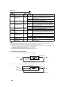
*2 Input terminal monitor details
*3 Output terminal monitor details
*4 When Pr.37 = "1 to 9998" or Pr. 144 = "2 to 10, 102 to 110," the unit is an integral value (one increment). (Refer to page 139)
*5 Option input terminal 1 monitor details (input terminal status of FR-A7AX) All OFF if option is not installed.
*6 Option input terminal 2 monitor details (input terminal status of FR-A7AX) All OFF if option is not installed.
*7 Option output terminal monitor details (output terminal status of FR-A7AY) All OFF if option is not installed.
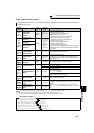
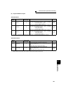
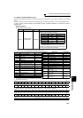
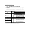
Register Definition Read/Write Remarks
40010
Operation mode/
inverter setting
Read/write
For write, set data as the operation mode setting. For read,
data is read as the operation mode status.
*
Writing is available depending on the Pr. 79 and Pr. 340 settings. Refer
to page 203 for details.
The restrictions depending on the operation mode changes
according to the computer link specifications.
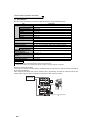
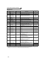
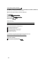
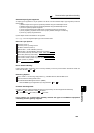
b15 b0
⎯⎯⎯⎯CS RES
STOP
MRS JOG RH RM RL RT AU STR STF
b15 b0
⎯⎯⎯⎯⎯⎯⎯⎯⎯
ABC2 ABC1
FU OL IPF SU RUN
b15 b0
X15 X14 X13 X12 X11 X10 X9 X8 X7 X6 X5 X4 X3 X2 X1 X0
b15 b0
⎯⎯⎯⎯⎯⎯⎯⎯⎯⎯⎯⎯⎯⎯⎯DY
b15 b0
⎯⎯⎯⎯⎯⎯RA3RA2RA1Y6Y5Y4Y3Y2Y1Y0
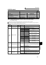
Mode Read Value Written Value
EXT H0000 H0010 *
PU H0001 H0011 *
EXT JOG H0002 ⎯
PU JOG H0003 ⎯
NET H0004 H0014
PU+EXT H0005 ⎯
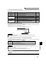
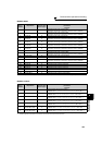
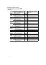
Register
Description Increments
40201 Output frequency/Speed
*4
0.01Hz/1
40202 Output current 0.01A/0.1A
*1
40203 Output voltage 0.1V
40205
Frequency setting value/Speed
setting
*4
0.01Hz/1
40206 Running speed 1r/min
40208 Converter output voltage 0.1V
40209 Regenerative brake duty 0.1%
40210
Electronic thermal relay function
load factor
0.1%
40211 Output current peak value 0.01A
/0.1A
*1
40212
Converter output voltage peak value
0.1V
40213 Input power
0.01kW/0.1kW
*1
40214 Output power
0.01kW/0.1kW
*1
40215 Input terminal status
*2
⎯
40216 Output terminal status
*3
⎯
40217 Load meter 0.1%
40220 Cumulative energization time 1h
40223 Actual operation time 1h
40224 Motor load factor 0.1%
40225 Cumulative power 1kWh
40250 Power saving effect Variable
40251 Cumulative saving power Variable
40252 PID set point 0.1%
40253 PID measured value 0.1%
40254 PID deviation 0.1%
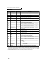
40258 Option input terminal status 1
*5
⎯
40259 Option input terminal status 2
*6
⎯
40260 Option output terminal status
*7
⎯
40267 PID measured value 2 0.1%
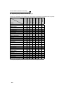
40277
32-bit cumulative power
(lower 16-bit)
1kWh
40278
32-bit cumulative power
(upper 16-bit)
1kWh
40279
32-bit cumulative power
(lower 16-bit)
0.01kWh/
0.1kWh
*1
40280
32-bit cumulative power
(upper 16-bit)
0.01kWh/
0.1kWh
*1
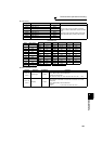
Register
Description Increments