


265
PID control
4
PARAMETERS
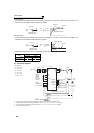
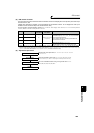
(4) I/O signals and parameter setting
⋅ Turn ON the X14 signal to perform PID control. When this signal is OFF, PID action is not performed and normal
inverter operation is performed. (However, turning X14 ON is not necessary when Pr.128 = "50, 51, 60, 61, 110,
111, 120, 121".)
⋅ Enter the set point across inverter terminals 2-5 or into Pr. 133 and enter the measured value signal across inverter
terminals 4 and 5. At this time, set any of "20, 21, 120, 121" in Pr. 128.
⋅ When entering the externally calculated deviation signal, enter it across terminals 1 and 5. At this time, set any of
"10, 11, 110, 111" in Pr. 128.
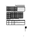
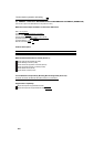
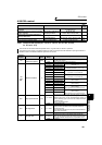
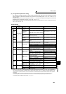
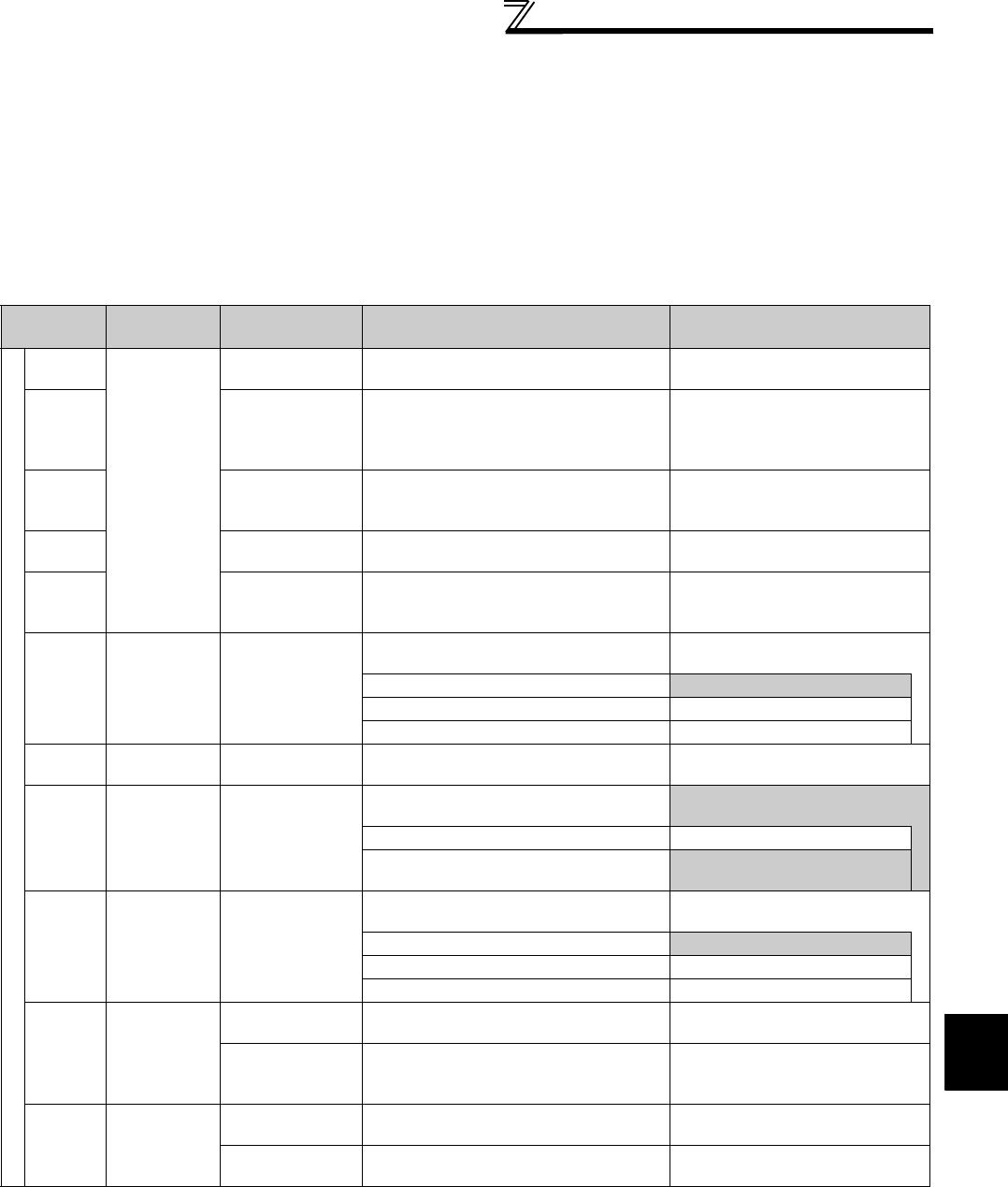
Input signals
Signal
Terminal
Used
Function Description Parameter Setting
Input
X14
Depending on
Pr. 178 to Pr.
189
PID control
selection
Turn ON X14 to perform PID control. Set 14 in any of Pr. 178 to Pr. 189.
X64
PID forward/
reverse action
switchover
By turning ON X64, forward action can be
selected for PID reverse action (
Pr. 128
=
10, 20, 110, 120), and reverse action for
forward action (
Pr. 128
= 11, 21, 111, 121).
Set 64 in any of Pr. 178 to Pr. 189.
X72
PID integral value
reset
ON: Integral and differential values are
reset
OFF: Normal processing
Set 72 in any of Pr. 178 to Pr. 189.
X77
Pre-charge end
command
Turn ON X77 to end the pre-charge
operation and start PID control.
Set 77 in any of Pr. 178 to Pr. 189.
X78
Second pre-
charge end
command
Turn ON X78 while RT is ON to end the
pre-charge operation and start PID
control.
Set 78 in any of Pr. 178 to Pr. 189.
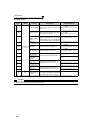
22Set point input
Enter the set point for PID control.
Pr. 128 = 20, 21, 120, 121
Pr. 133 =9999
0 to 5V................0 to 100%
Pr. 73 = 1 *1, 3, 5, 11, 13, 15
0 to 10V..............0 to 100%
Pr. 73 = 0, 2, 4, 10, 12, 14
0 to 20mA...........0 to 100%
Pr. 73 = 6, 7, 16, 17
PU ⎯ Set point input
Set the set value (Pr. 133) from the
operation panel or parameter unit.
Pr. 128 = 20, 21, 120, 121
Pr. 133 = 0 to 100%
11
Deviation signal
input
Input the deviation signal calculated
externally.
Pr. 128 = 10 *1, 11, 110, 111
-5V to +5V..........-100% to +100%
Pr. 73 = 2, 3, 5, 7, 12, 13, 15, 17
-10V to +10V......-100% to +100%
Pr. 73 = 0, 1 *1, 4, 6, 10, 11, 14,
16
44
Measured value
input
Input the signal from the detector
(measured value signal).
Pr. 128 = 20, 21, 120, 121
4 to 20mA...........0 to 100%
Pr. 267 = 0 *1
0 to 5V................0 to 100%
Pr. 267 = 1
0 to 10V..............0 to 100%
Pr. 267 = 2
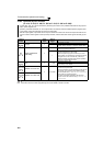
Communi-
cation
*2
⎯
Deviation value
input
Input the deviation value from L
ON
W
ORKS
,
CC-Link
, or BACnet
communication.
Pr. 128 = 50, 51
Set value,
measured value
input
Input the set value and measured value
from L
ONWORKS , CC-Link, or BACnet
communication.
Pr. 128 = 60, 61
PLC ⎯
Deviation value
input
Input the deviation value from PLC
function.
Pr. 128 = 70, 71, 90, 91
Set value, measured
value input
Input the set value and measured value
from PLC function.
Pr. 128 = 80, 81, 100, 101
*1 The shaded area indicates the parameter initial value.
*2 When Pr. 128 = "50, 51, 60, 61" and the operation mode is not NET, input method is same as when Pr. 128 = "10, 11, 20, 21" respectively.
Input from BACnet communication is available when the operation mode is NET, Pr. 549 = "2" (BACnet), and RS-485 terminal has the
command source. Input from LonWorks or CC-Link communication is available when BACnet communication is inactive and the operation
mode is NET.
For the setting method via L
ONWORKS communication, refer to the LONWORKS communication option (FR-A7NL) instruction manual.
For the setting method via CC-Link communication, refer to the CC-Link communication option (FR-A7NC) instruction manual.
For the setting method via BACnet communication, refer to page 247.