


Product Preview DS21Q55
110 of 248 012103
Please contact telecom.support@dalsemi.com or search http://www.maxim-ic.com for updated
information.
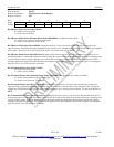
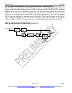
18.1 Receive Side
See the IOCR1 and IOCR2 registers for information on clock and I/O configurations.
If the receive-side elastic store is enabled, then the user must provide either a 1.544MHz or 2.048MHz
clock at the RSYSCLK pin. For higher rate system-clock applications, see the Interleaved PCM Bus
Operation section. The user has the option of either providing a frame/multiframe sync at the RSYNC pin
or having the RSYNC pin provide a pulse on frame/multiframe boundaries. If signaling reinsertion is
enabled, signaling data in TS16 is realigned to the multiframe-sync input on RSYNC. Otherwise, a
multiframe-sync input on RSYNC is treated as a simple frame boundary by the elastic store. The framer
will always indicate frame boundaries on the network side of the elastic store via the RFSYNC output
whether the elastic store is enabled or not. Multiframe boundaries will always be indicated via the
RMSYNC output. If the elastic store is enabled, then RMSYNC will output the multiframe boundary on
the backplane side of the elastic store.
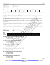
18.1.1 T1 Mode
If the user selects to apply a 2.048MHz clock to the RSYSCLK pin, then the data output at RSER will be
forced to all ones every fourth channel and the F-bit will be passed into the MSB of TS0. Hence, channels
1 (bits 1–7), 5, 9, 13, 17, 21, 25, and 29 (timeslots 0 (bits 1-7), 4, 8, 12, 16, 20, 24, and 28) will be forced
to a one. Also, in 2.048MHz applications, the RCHBLK output will be forced high during the same
channels as the RSER pin. This is useful in T1 to E1 conversion applications. If the two-frame elastic
buffer either fills or empties, a controlled slip will occur. If the buffer empties, then a full frame of data
will be repeated at RSER and the SR5.0 and SR5.1 bits will be set to a one. If the buffer fills, then a full
frame of data will be deleted and the SR5.0 and SR5.2 bits will be set to a one.
18.1.2 E1 Mode
If the elastic store is enabled, then either CAS or CRC4 multiframe boundaries will be indicated via the
RMSYNC output. If the user selects to apply a 1.544MHz clock to the RSYSCLK pin, then every fourth
channel of the received E1 data will be deleted and a F-bit position (which will be forced to one) will be
inserted. Hence, channels 1, 5, 9, 13, 17, 21, 25, and 29 (timeslots 0, 4, 8, 12, 16, 20, 24, and 28) will be
deleted from the received E1 data stream. Also, in 1.544MHz applications, the RCHBLK output will not
be active in channels 25 through 32 (or in other words, RCBR4 is not active). If the two-frame elastic
buffer either fills or empties, a controlled slip will occur. If the buffer empties, then a full frame of data
will be repeated at RSER and the SR5.0 and SR5.1 bits will be set to a one. If the buffer fills, then a full
frame of data will be deleted and the SR5.0 and SR5.2 bits will be set to a one.