


Product Preview DS21Q55
233 of 248 012103
Please contact telecom.support@dalsemi.com or search http://www.maxim-ic.com for updated
information.
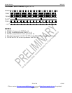
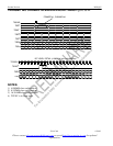
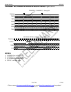
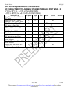
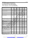
34. AC TIMING PARAMETERS AND DIAGRAMS
Capacitive test loads are 40pF for bus signals, 20pF for all others.
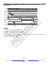
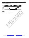
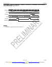
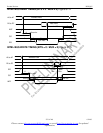
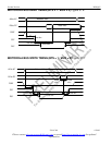
34.1 Multipexed Bus AC Characteristics
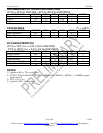
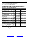
AC CHARACTERISTICS–MULTIPLEXED PARALLEL PORT (MUX = 1)
(0°C to +70°C; V
DD
= 3.3V ± 5% for DS21Q55;
-40°C to +85°C; V
DD
= 3.3V ± 5% for DS21Q55N)
PARAMETER SYMBOL
MIN TYP MAX UNITS NOTES
Cycle Time T
CYC
200 ns
Pulse Width, DS Low or RD*
High
PW
EL
100 ns
Pulse Width, DS High or RD*
Low
PW
EH
100 ns
Input Rise/Fall Times T
R
, t
F
20 ns
R/W* Hold Time T
RWH
10 ns
R/W* Setup Time Before DS
High
T
RWS
50 ns
CS* Setup Time Before DS,
WR* or RD* Active
t
CS
20 ns
CS* Hold Time t
CH
0 ns
Read Data Hold Time T
DHR
10 50 ns
Write Data Hold Time T
DHW
5 ns
Muxed Address Valid to AS or
ALE Fall
T
ASL
15 ns
Muxed Address Hold Time T
AHL
10 ns
Delay Time DS, WR*, or RD*
to AS or ALE Rise
T
ASD
20 ns
Pulse Width AS or ALE High PW
ASH
30 ns
Delay Time, AS or ALE to DS,
WR* or RD*
T
ASED
10 ns
Output Data Delay Time from
DS or RD*
T
DDR
80 ns
Data Setup Time T
DSW
50 ns
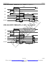
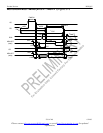
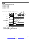
See Figures 37-1 to 37-3