


Product Preview DS21Q55
184 of 248 012103
Please contact telecom.support@dalsemi.com or search http://www.maxim-ic.com for updated
information.
25.3 BERT Bit Counter
Once BERT has achieved synchronization, this 32-bit counter will increment for each data bit (i.e., clock)
received. Toggling the LC control bit in BC1 can clear this counter, which saturates when full and will set
the BBCO status bit.
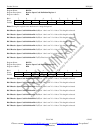
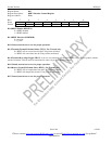
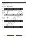
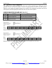
Register Name: BBC1
Register Description: BERT Bit Count Register 1
Register Address: E3h
Bit # 7 6 5 4 3 2 1 0
Name BBC7 BBC6 BBC5 BBC4 BBC3 BBC2 BBC1 BBC0
Default 0 0 0 0 0 0 0 0
Bits 0 to 7/BERT Bit Counter Bits 0 to 7 (BBC0 to BBC7). BBC0 is the LSB of the 32-bit counter.
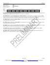
Register Name: BBC2
Regis ter Description: BERT Bit Count Register 2
Register Address: E4h
Bit # 7 6 5 4 3 2 1 0
Name BBC15 BBC14 BBC13 BBC12 BBC11 BBC10 BBC9 BBC8
Default 0 0 0 0 0 0 0 0
Bits 0 to 7/BERT Bit Counter Bits 8 to 15 (BBC8 to BBC15).
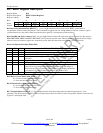
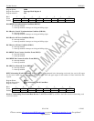
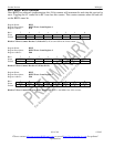
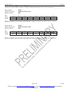
Register Name: BBC3
Register Description: BERT Bit Count Register 3
Register Address: E5h
Bit # 7 6 5 4 3 2 1 0
Name BBC23 BBC22 BBC21 BBC20 BBC19 BBC18 BBC17 BBC16
Default 0 0 0 0 0 0 0 0
Bits 0 to 7/BERT Bit Counter Bits 16 to 23 (BBC16 to BBC23).
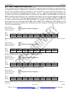
Register Name: BBC4
Register Description: BERT Bit Count Register 4
Register Address: E6h
Bit # 7 6 5 4 3 2 1 0
Name BBC31 BBC30 BBC29 BBC28 BBC27 BBC26 BBC25 BBC24
Default 0 0 0 0 0 0 0 0
Bits 0 to 7/BERT Bit Counter Bits 24 to 31 (BBC24 to BBC31). BBC31 is the MSB of the 32-bit counter.