


Product Preview DS21Q55
97 of 248 012103
Please contact telecom.support@dalsemi.com or search http://www.maxim-ic.com for updated
information.
16. PER-CHANNEL IDLE CODE GENERATION
Channel data can be replaced by an idle code on a per-channel basis in the transmit and receive
directions. When operated in the T1 mode, only the first 24 channels are used; the remaining channels,
CH25–CH32 are not used.
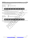
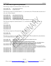
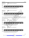
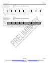
The DS21Q55 contains a 64-byte idle code array accessed by the idle array address register (IAAR) and
the per-channel idle code register (PCICR). The contents of the array contain the idle codes to be
substituted into the appropriate transmit or receive channels. This substitution can be enabled and
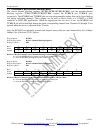
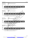
disabled on a per-channel basis by the transmit-channel idle-code enable registers (TCICE1–4) and
receive-channel idle-code enable registers (RCICE1–4).
To program idle codes, first select a channel by writing to the IAAR register. Then write the idle code to
the PCICR register. For successive writes there is no need to load the IAAR with the next consecutive
address. The IAAR register will automatically increment after a write to the PCICR register. The auto
increment feature can be used for read operations as well.
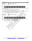
Bits 6 and 7 (GTIC, GRIC) of the IAAR register can be used to block write a common idle code to all
transmit or receive positions in the array with a single write to the PCICR register. The user can use the
block write feature to set a common idle code for all transmit and receive channels in the IAAR by setting
both GTIC and GRIC = 1. When a block write is enabled by GTIC or GRIC, the value placed in the
PCICR register will be written to all addresses in the transmit or receive idle array and to whatever
address is in the lower 6 bits of the IAAR register. Therefore, when enabling only one of the block
functions, GTIC or GRIC, the user must set the lower 6 bits of the IAAR register to any address in that
block. Bits 6 and 7 of the IAAR register must be set = 0 for read operations.
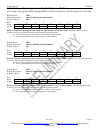
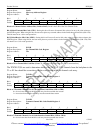
The TCICE1–4 and RCICE1–4 are used to enable idle-code replacement on a per-channel basis.
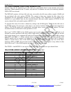
IDLE CODE ARRAY ADDRESS MAPPING Table 18-1
BITS 0–5 OF IAAR REGISTER MAPS TO CHANNEL
0 Transmit Channel 1
1 Transmit Channel 2
2 Transmit Channel 3
-
-
30 Transmit Channel 31
31 Transmit Channel 32
32 Receive Channel 1
33 Receive Channel 2
34 Receive Channel 3
-
-
62 Receive Channel 31
63
Receive Channel 32