


Product Preview DS21Q55
51 of 248 012103
Please contact telecom.support@dalsemi.com or search http://www.maxim-ic.com for updated
information.
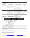
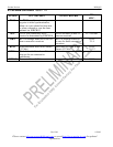
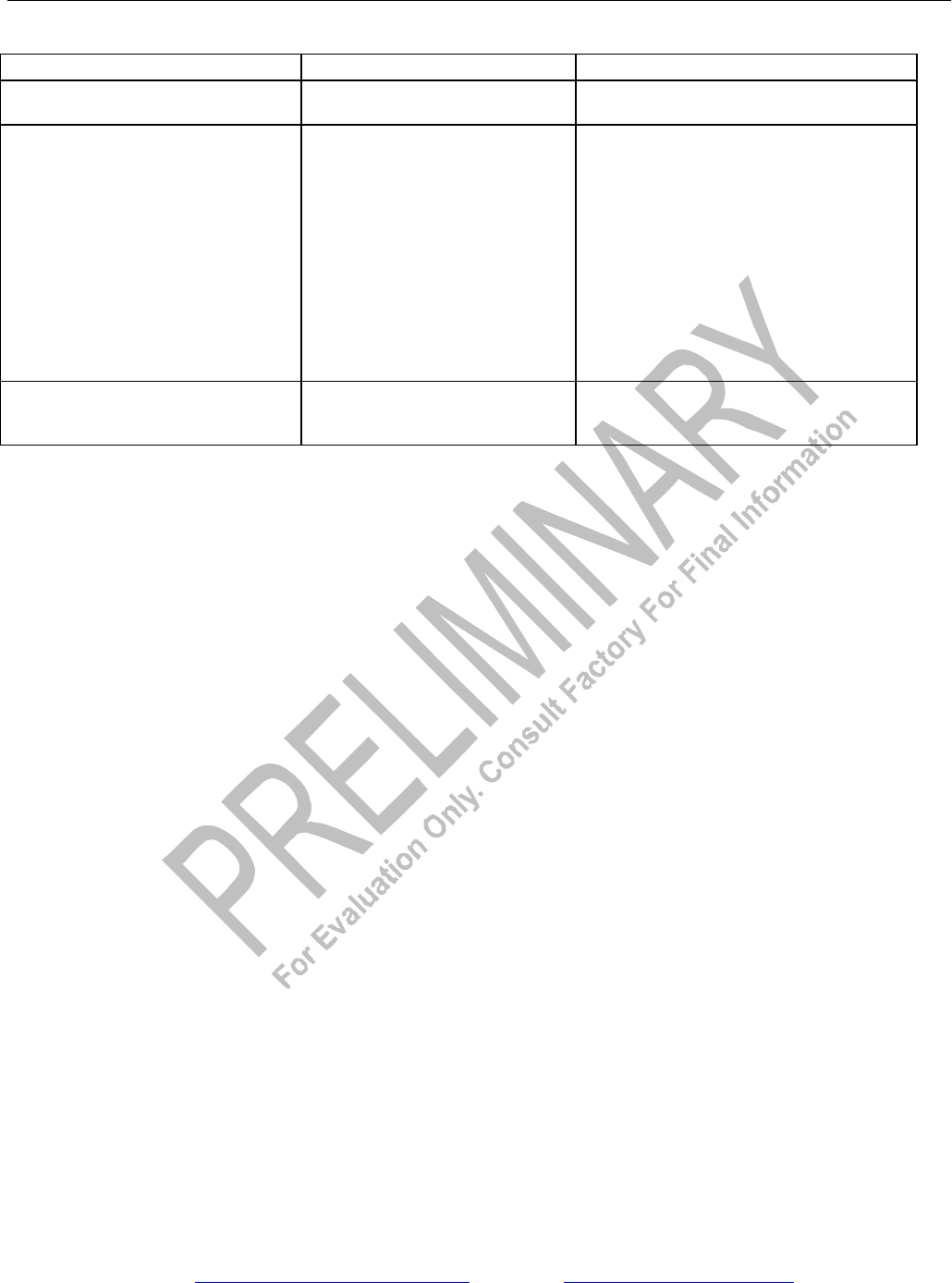
T1 ALARM CRITERIA Table 10-1
ALARM SET CRITERIA CLEAR CRITERIA
Blue Alarm (AIS) (Note 1) Over a 3ms window, five or fewer
zeros are received
Over a 3ms window, six or more zeros are
received
Yellow Alarm (RAI)
D4 Bit-2 Mode (T1RCR2.0 = 0)
D4 12th F-bit Mode (T1RCR2.0 = 1;
this mode is also referred to as the
“Japanese Yellow Alarm”)
ESF Mode
Bit 2 of 256 consecutive channels
is set to zero for at least 254
occurrences
12th framing bit is set to one for
two consecutive occurrences
16 consecutive patterns of 00FF
appear in the FDL
Bit 2 of 256 consecutive channels is set to
zero for less than 254 occurrences
12th framing bit is set to zero for two
consecutive occurrences
14 or fewer patterns of 00FF hex out of 16
possible appear in the FDL
Red Alarm (LRCL) (Also referred to
as Loss Of Signal)
192 consecutive zeros are
received
14 or more ones out of 112 possible bit
positions are received, starting with the
first one received
NOTES:
1) The definition of blue alarm (or alarm indication signal) is an unframed, all-ones signal. Blue alarm
detectors should be able to operate properly in the presence of a 10E-3 error rate, and they should not
falsely trigger on a framed, all-ones signal. The blue alarm criteria in the DS21Q55 has been set to
achieve this performance. It is recommended that the RBL bit be qualified with the RLOS bit.
2) ANSI specifications use a different nomenclature than this data sheet does; the following terms are
equivalent:
RBL = AIS
RCL = LOS
RLOS = LOF
RYEL = RAI