


Product Preview DS21Q55
45 of 248 012103
Please contact telecom.support@dalsemi.com or search http://www.maxim-ic.com for updated
information.
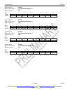
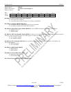
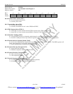
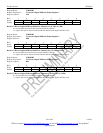
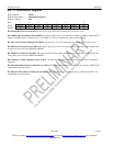
Register Name: T1TCR1
Register Description: T1 Transmit Control Register 1
Register Address: 05h
Bit # 7 6 5 4 3 2 1 0
Name TJC TFPT TCPT TSSE GB7S TFDLS TBL TYEL
Default 0 0 0 0 0 0 0 0
Bit 0/Transmit Yellow Alarm (TYEL).
0 = do not transmit yellow alarm
1 = transmit yellow alarm
Bit 1/Transmit Blue Alarm (TBL).
0 = transmit data normally
1 = transmit an unframed all one’s code at TPOS and TNEG
Bit 2/TFDL Register Select (TFDLS).
0 = source FDL or Fs bits from the internal TFDL register (legacy FDL support mode)
1 = source FDL or Fs bits from the internal HDLC controller or the TLINK pin
Bit 3/Global Bit 7 Stuffing (GB7S).
0 = allow the SSIEx registers to determine which channels containing all zeros are to be Bit 7 stuffed
1 = force Bit 7 stuffing in all zero byte channels regardless of how the SSIEx registers are programmed
Bit 4/Transmit Software Signaling Enable (TSSE).
0 = do not source signaling data from the TSx registers regardless of the SSIEx registers. The SSIEx registers still
define which channels are to have B7 stuffing preformed
1 = source signaling data as enabled by the SSIEx registers
Bit 5/Transmit CRC Pass Through (TCPT).
0 = source CRC6 bits internally
1 = CRC6 bits sampled at TSER during F-bit time
Bit 6/Transmit F-Bit Pass Through (TFPT).
0 = F bits sourced internally
1 = F bits sampled at TSER
Bit 7/Transmit Japanese CRC6 Enable (TJC).
0 = use ANSI/AT&T/ITU CRC6 calculation (normal operation)
1 = use Japanese standard JT–G704 CRC6 calculation