


Product Preview DS21Q55
52 of 248 012103
Please contact telecom.support@dalsemi.com or search http://www.maxim-ic.com for updated
information.
9. E1 FRAMER/FORMATTER CONTROL REGISTERS
The E1 framer portion of the DS21Q55 is configured via a set of four control registers. Typically, the
control registers are only accessed when the system is first powered up. Once the device has been
initialized, the control registers will only need to be accessed when there is a change in the system
configuration. There are two receive control registers (E1RCR1 and E1RCR2) and two transmit control
registers (E1TCR1 and E1TCR2). There are also four status and information registers. Each of these eight
registers are described in this section.
9.1 E1 Control Registers
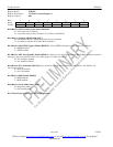
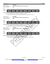
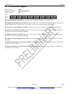
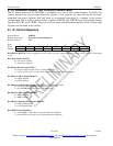
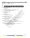
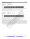
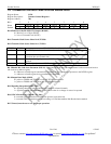
Register Name: E1RCR1
Register Description: E1 Receive Control Register 1
Register Address: 33h
Bit # 7 6 5 4 3 2 1 0
Name RSERC RSIGM RHDB3 RG802 RCRC4 FRC SYNCE RESYNC
Default 0 0 0 0 0 0 0 0
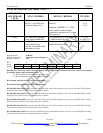
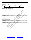
Bit 0/Resync (RESYNC). When toggled from low to high, a resync is initiated. Must be cleared and set again for a subsequent
resync.
Bit 1/Sync Enable (SYNCE).
0 = auto resync enabled
1 = auto resync disabled
Bit 2/Frame Resync Criteria (FRC).
0 = resync if FAS received in error 3 consecutive times
1 = resync if FAS or bit 2 of non-FAS is received in error three consecutive times
Bit 3/Receive CRC4 Enable (RCRC4).
0 = CRC4 disabled
1 = CRC4 enabled
Bit 4/Receive G.802 Enable (RG802). See Signaling Operation for details.
0 = do not force RCHBLK high during bit 1 of timeslot 26
1 = force RCHBLK high during bit 1 of timeslot 26
Bit 5/Receive HDB3 Enable (RHDB3).
0 = HDB3 disabled
1 = HDB3 enabled
Bit 6/Receive Signaling Mode Select (RSIGM).
0 = CAS signaling mode
1 = CCS signaling mode
Bit 7/RSER Control (RSERC).
0 = allow RSER to output data as received under all conditions
1 = force RSER to one under loss of frame alignment conditions