


Product Preview DS21Q55
54 of 248 012103
Please contact telecom.support@dalsemi.com or search http://www.maxim-ic.com for updated
information.
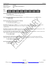
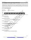
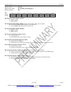
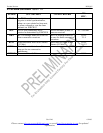
Register Name: E1TCR1
Register Description: E1 Transmit Control Register 1
Register Address: 35h
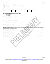
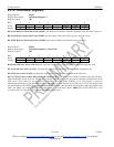
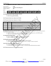
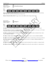
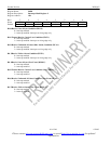
Bit # 7 6 5 4 3 2 1 0
Name TFPT T16S TUA1 TSiS TSA1 THDB3 TG802 TCRC4
Default 0 0 0 0 0 0 0 0
Bit 0/Transmit CRC4 Enable (TCRC4).
0 = CRC4 disabled
1 = CRC4 enabled
Bit 1/Transmit G.802 Enable (TG802). See Functional Timing Diagrams for details.
0 = do not force TCHBLK high during bit 1 of timeslot 26
1 = force TCHBLK high during bit 1 of timeslot 26
Bit 2/Transmit HDB3 Enable (THDB3).
0 = HDB3 disabled
1 = HDB3 enabled
Bit 3/Transmit Signaling All Ones (TSA1).
0 = normal operation
1 = force timeslot 16 in every frame to all ones
Bit 4/Transmit International Bit Select (TSiS).
0 = sample Si bits at TSER pin
1 = source Si bits from TAF and TNAF registers (in this mode, E1TCR1.7 must be set to zero)
Bit 5/Transmit Unframed All Ones (TUA1).
0 = transmit data normally
1 = transmit an unframed all one’s code at TPOSO and TNEGO
Bit 6/Transmit Timeslot 16 Data Select (T16S). See Transmit Signaling for details
0 = timeslot 16 determined by the SSIEx registers and the THSCS function in the PCPR register
1 = source timeslot 16 from TS1 to TS16 registers
Bit 7/Transmit Timeslot 0 Pass Through (TFPT).
0 = FAS bits/Sa bits/Remote Alarm sourced internally from the TAF and TNAF registers
1 = FAS bits/Sa bits/Remote Alarm sourced from TSER