


Product Preview DS21Q55
182 of 248 012103
Please contact telecom.support@dalsemi.com or search http://www.maxim-ic.com for updated
information.
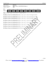
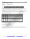
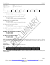
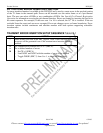
Register Name: IMR9
Register Description: Interrupt Mask Register 9
Register Address: 27h
Bit # 7 6 5 4 3 2 1 0
Name - BBED BBCO BEC0 BRA1 BRA0 BRLOS BSYNC
Default 0 0 0 0 0 0 0 0
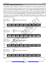
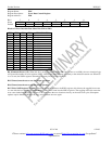
Bit 0/BERT in Synchronization Condition (BSYNC).
0 = interrupt masked
1 = interrupt enabled–interrupts on rising and falling edges
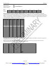
Bit 1/Receive Loss Of Synchronization Condition (BRLOS).
0 = interrupt masked
1 = interrupt enabled–interrupts on rising and falling edges
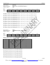
Bit 2/Receive All Zeros Condition (BRA0).
0 = interrupt masked
1 = interrupt enabled–interrupts on rising and falling edges
Bit 3/Receive All Ones Condition (BRA1).
0 = interrupt masked
1 = interrupt enabled–interrupts on rising and falling edges
Bit 4/BERT Error Counter Overflow Event (BECO).
0 = interrupt masked
1 = interrupt enabled
Bit 5/BERT Bit Counter Overflow Event (BBCO).
0 = interrupt masked
1 = interrupt enabled
Bit 6/Bit Error Detected Event (BBED).
0 = interrupt masked
1 = interrupt enabled
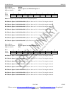
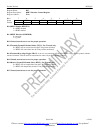
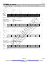
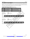
BERT Alternating Word Count Rate. When the BERT is programmed in the alternating word mode, the words will repeat
for the count loaded into this register then flip to the other word and again repeat for the number of times loaded into this
register
Register Name: BAWC
Register Description: BERT Alternating Word Count Rate
Register Address: DBh
Bit # 7 6 5 4 3 2 1 0
Name ACNT7 ACNT6 ACNT5 ACNT4 ACNT3 ACNT2 ACNT1 ACNT0
Default 0 0 0 0 0 0 0 0
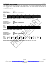
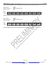
Bits 0 to 7/Alternating Word Count Rate Bits 0 to 7 (ACNT0 to ACNT7). ACNT0 is the LSB of the 8-bit alternating word
count rate counter.