


Product Preview DS21Q55
121 of 248 012103
Please contact telecom.support@dalsemi.com or search http://www.maxim-ic.com for updated
information.
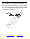
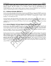
21.3 Internal Register Scheme Based On CRC4 Multiframe (Method 3)
On the receive side, there is a set of eight registers (RSiAF, RSiNAF, RRA, RSa4 to RSa8) that report the
Si and Sa bits as they are received. These registers are updated with the setting of the receive CRC4
multiframe bit in status register 2 (SR4.1). The host can use the SR4.1 bit to know when to read these
registers. The user has 2ms to retrieve the data before it is lost. The MSB of each register is the first
received. Please see the following register descriptions for more details.
On the transmit side, there is also a set of eight registers (TSiAF, TSiNAF, TRA, TSa4 to TSa8) that via
the transmit Sa bit control register (TSaCR), can be programmed to insert both Si and Sa data. Data is
sampled from these registers with the setting of the transmit multiframe bit in status register 2 (SR4.4).
The host can use the SR4.4 bit to know when to update these registers. It has 2ms to update the data or
else the old data will be retransmitted. The MSB of each register is the first bit transmitted. See the
following register descriptions for details.
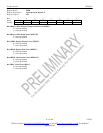
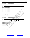
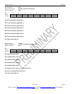
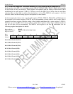
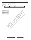
Register Name: RSiAF
Register Description: Receive Si Bits of the Align Frame
Register Address: C8h
Bit # 7 6 5 4 3 2 1 0
Name SiF0 SiF2 SiF4 SiF6 SiF8 SiF10 SiF12 SiF14
Default 0 0 0 0 0 0 0 0
Bit 0/Si Bit of Frame 14(SiF14).
Bit 1/Si Bit of Frame 12(SiF12).
Bit 2/Si Bit of Frame 10(SiF10).
Bit 3/Si Bit of Frame 8(SiF8).
Bit 4/Si Bit of Frame 6(SiF6).
Bit 5/Si Bit of Frame 4(SiF4).
Bit 6/Si Bit of Frame 2(SiF2).
Bit 7/Si Bit of Frame 0(SiF0).